Bonfiglioli EM-RES-02 Expansion Module
The manual (version 08/06, R02) for the expansion module of the Bangfeili Vectron ACT/ACU (ACTION/ACTION Cube) frequency converter EM-RES-02 option describes the hardware, safety requirements, mechanical and electrical installation, IO functions, parameters, and fault information of the option. The EM-RES-02 is an optional plug-in module that adds a rotary transformer interface, a second bipolar analog input, and repetitive frequency output function to the frequency converter.
Overview and Safety Regulations
System
The materials for Bangfeili frequency converters are divided into four categories: brief installation instructions, operation manuals, application manuals, and installation instructions; This manual is only for the EM-RES-02 module and is not intended as a complete operation manual for the frequency converter. Module support: ACU full series; ACT frequency converter requires firmware version ≥ 4.1.0. The document uses level 4 warning signs:
Danger! Danger: Direct fatal danger;
Warning! Warning: Potential risk of fatal injury;
Caution! Caution: Risk of personal/equipment damage;
Attention! Attention: Abnormal working status prompt;
Note: Auxiliary operation information.
The operator must be a qualified professional, familiar with the installation and commissioning of frequency converters, and familiar with relevant IEC, EN, VDE, BGV A2 and other standards.
General safety and usage conditions
Correct use: Frequency converters belong to industrial equipment components and must comply with the EU Machinery Directive and Low Voltage Directive; The EMC compliance responsibility is borne by the equipment manufacturer; UL508c and CSA C22.2-N.14-95 certification meet the requirements. Prohibited for use in non industrial professional settings.
Transportation and storage: using original factory packaging, in a dry, dust-proof, and low temperature difference environment; Storage without power for up to 1 year.
Handling: The equipment is equipped with static sensitive components, and touching the circuit board is prohibited; Damaged equipment must not be powered on.
Mandatory requirements for electrical work:
All wiring disassembly and assembly must be completely powered off;
After a power outage, it is necessary to wait for several minutes for the DC bus capacitor to discharge completely. Even after the bus and motor terminals are powered off, they still carry dangerous high voltage;
Signal cables cannot be directly subjected to high-voltage insulation testing, and the circuit needs to be disconnected first.
Operation and maintenance: Wiring is not allowed during operation; Repairs can only be carried out by the manufacturer or authorized personnel.
Introduction to EM-RES-02 module
Provide three major hardware functions
Second bipolar analog input EM-S1INA;
The input of the rotary transformer encoder EM-RES;
Repetitive frequency output EM-RFOUT (simulated incremental encoder).
The module is an independent accessory that can be plugged into the bottom slot of the frequency converter when powered off. Once plugged in, it can be turned on and activated.
Mechanical and Electrical Installation
Mechanical Installation
The frequency converter is completely powered off and waiting for the capacitor to discharge;
Remove the lower cover plate of the frequency converter;
Align the EM-RES-02 module with the bottom slot and insert it; ⚠️ Do not touch the PCB circuit board on the back of the module, as static electricity can damage the hardware;
Restore the lower cover plate and prepare the power module.
Electrical Interface
Module wiring terminals: X410A, X410B, Wieland DST85/RM3.5 terminals, tightening torque 0.2-0.3 Nm.
Requirements for twisted pair shielded cables: SIN+/SIN – pair, COS+/COS – pair, excitation wire pair; Both ends of the shielding layer are connected to PE protective ground.
X410A terminal
Terminal signal
1 EM-RES REF+Rotary Excitation+
2 EM RES REF Rotary Excitation
3 EM‑RES SIN‑
4 EM‑RES SIN+
5 EM‑RES COS‑
6 EM‑RES COS+
7 EM‑RFOUT A+
X410B terminal
Terminal signal
1 EM‑RFOUT A‑
2 EM‑RFOUT B+
3 EM‑RFOUT B‑
4 EM-S1INA analog input
5 EM-RFOUT R+(zero position reference)
6 EM‑RFOUT R‑
7 GND Ground
Hardware electrical specifications
The effective excitation value of the Resolver interface is Uref=4 V, with a maximum current of 60 mA. It supports excitation frequencies of 5/10/20 kHz, with a maximum number of pole pairs of 24 and a maximum speed of 30000 rpm for one pair of poles.
EM-RFOUT repetition frequency output RS-422A/TTL push-pull output, up to 512kHz, simulated incremental encoder, fixed 1024 lines, with zero position R signal; Anti -5V~+10V interference voltage.
EM-S1INA analog input with 12 bit resolution;
Voltage mode: ± 10 V, input impedance 100 k Ω;
Current mode: ± 20 mA, input impedance 250 Ω; Onboard dip switch S3: OFF=voltage input; ON=current input, factory default voltage mode.
Detailed functions of control input and output
Analog input EM-S1INA
Analog inputs can be used as: frequency given source, percentage given source, actual percentage source, and limit source. Select the purpose for parameters 475, 476, 478, 734-737.
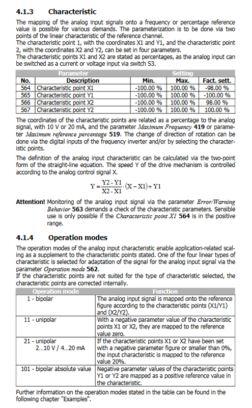
Characteristic curve (two-point calibration) parameters 564 (X1), 565 (Y1), 566 (X2), 567 (Y2) define linear curves; X/Y is expressed as a percentage; Linear formula:
\(Y=\frac{Y2‑Y1}{X2‑X1}·(X‑X1)+Y1\)
Four working modes (parameter 562)
Mode Name Function Description
1 Bipolar Bipolar Two point Fully Free Mapping, Supports Positive and Negative Given, Reversible
11 Unipolar X Negative Input Forced Mapping Given 0
21 unipolar 2-10V/4-20mA adapted to industrial standard current and voltage signals, input mapping starting point 20%
101 Bipolar Absolute Value takes the input absolute value and will not cause any steering changes
The document includes calculation examples for each mode.
Scaling parameters 418 minimum frequency, 419 maximum frequency; 518 minimum reference percentage, 519 maximum reference percentage, define the output range.
Tolerance zone and hysteresis (560 tolerance zone) are used for zero crossing, setting a dead zone near the zero point, and combining with the minimum frequency parameter to achieve hysteresis and suppress zero jitter. Set range 0-25%.
Fault/Warning Behavior 563: When the monitoring input is below 1V/2mA, actions will be taken: turn off monitoring, alarm, slow down and stop, and stop freely due to fault.
Input calibration 568 is used to compensate for device deviations: 0V/0mA calibration, 10V/20mA calibration. External application of standard signals is required.
Low pass filtering with a filtering time constant of 561 suppresses interference, with multiple selectable ranges from 0 to 5000ms; 0ms represents filtering off.
Resolver Rotation Input EM-RES
Used for synchronous motor rotor position detection.
parameter
380: Rotary excitation frequency selection of 5 kHz/10 kHz/20 kHz;
381: Rotation pole pairs (1-24);
382: The rotor offset angle Offset -360 °~+360 ° must be calibrated for synchronous motors to ensure torque and smooth operation.
Requirements for synchronous motors: The number of motor poles/number of rotor poles must be an integer.
Offset offset calibration complete steps
Safety prerequisite: Enable the release of the controller; Try to detach the load as much as possible; Set a low shutdown frequency limit of 417; Set the speed loop current limit of 728 to a low value to prevent runaway.
Manually rotate the motor shaft and check 219 (frequency of speed sensor 2) to confirm the direction of rotation; Reverse the direction and switch to SIN+/SIN -.
Given low speed, start the motor; Adjust Offset based on motor phenomenon:
Motor not turning: check the number of pole pairs parameter; It is necessary to switch the two phases of the motor; Offset increases by 90 °/(number of motor poles);
F1100 overspeed fault: Offset increases by 180 °/(number of motor poles);
Motor rotates normally: Adjust Offset slightly until the magnetizing voltage is 235 ≈ 0; Positive values increase offset, negative values decrease offset.
Restore the limit parameters, reset the Offset at the rated frequency, and execute the boot debugging SETUP after completion.
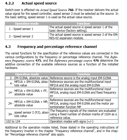
Actual speed source 766
1: Speed sensor 1 (inverter body, factory default)
2: Speed sensor 2 (EM-RES-02 rotary converter, this option must be selected when using rotary converter as speed feedback)
Given channel
Parameter 475 refers to the frequency source and 476 refers to the percentage source, and the EM S1INA analog quantity can be used as a given; It is also possible to combine multifunctional inputs MFI1A, fixed frequency FF, motor potentiometer MP, or use the variable speed as a given source. Supports signed/absolute value mode.
Actual Value Display Parameters
219: Speed sensor 2 frequency (Hz)
220: Speed sensor 2 speed (rpm)
253: EM-S1INA Analog Input Percentage Value
EM-RFOUT Repetitive Frequency Output
Simulate incremental encoder output with fixed 1024 pulses per revolution, with A/B/R zero position signals; No parameter settings required, output directly.
module related fault codes
Suggestions for troubleshooting the meaning of fault numbers
F14-21 Rotary Transformer Synchronization Failure Check for Rotary Transformer Cable Interference
F14-22 rotary counting error signal interference, check wiring shielding
F14-23 illegal motor/ratio of variable pole pairs must be an integer, check parameters 373 and 381
F14-24 Rotary Transformer Open Circuit Inspection: Rotary Transformer Wiring and Cable Breaks
If an unlisted fault occurs, please contact Bangfeili technical support.