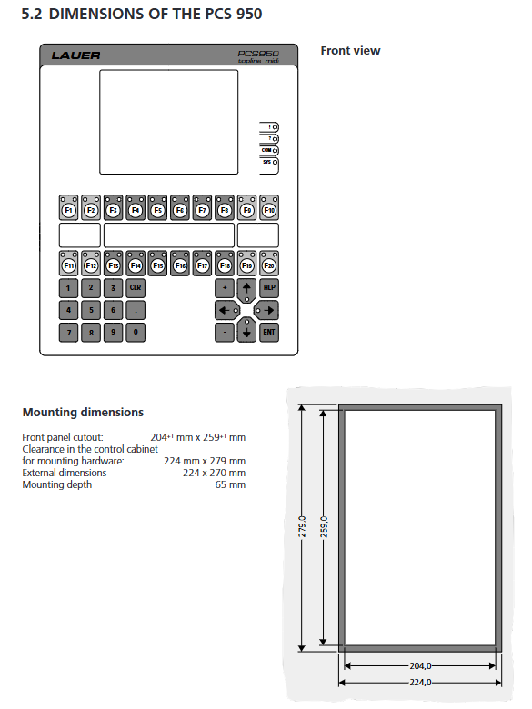
Lauer PCS950/PCS950c/PCS950e operation console
Hardware part
1.1 Hardware Layout
Display screen: PCS950 is 320 × 240; PCS950e resolution 240 × 128; PCS950c color screen.
Button: 20 function keys F1-F20 (each button comes with two green and yellow LEDs, supporting four states: normally off, normally on, flashing, and reverse flashing); Number keys 0-9; CLR clearing, ENT confirmation, HLP help, directional cursor keys.
There are a total of 4 panel status LEDs:
!: Alarm/Fault Activation
?: Operator input waiting
COM: Communication status, constantly on=communication not established, flashing=communication interrupted
SYS: BIOS system running (firmware not loaded/maintenance mode)
Backboard: 10 DIP dip switch, reset button; Multiple sets of SUB-D communication interfaces; 32 pin expansion card slot; 24VDC power supply terminal; Relay alarm output contact.
1.2 DIP dip switch function
Switch function
1-4 firmware custom PLC bit
5-6 driver configuration (baud rate, interface type, refer to the corresponding PLC driver manual PCS9.xxx)
7 PCSPROWIN programming baud rate: ON=115.0kBaud; OFF=38.5kBaud
8 Operation mode: OFF=normal operation; ON=Stop maintenance mode (must be set to OFF for normal operation)
9-10 Flash EEPROM write protection: ON allows writing, but the running state must be switched to OFF for write protection
When downloading the program, set it to ON on 9-10 and switch back to OFF after downloading to prevent accidental rewriting.
1.3 Interface
Power supply:+24VDC ± 20%, reverse polarity protection; Power consumption PCS950 typically 800mA, PCS950e control unit 1400mA; fuse 1.25A slow melting. The protective ground must be isolated from the 0V power supply, and the casing must be reliably grounded with a grounding wire of ≥ 4mm ².
PRO/COM port (15 pin): Can be configured with RS422/RS485 for PLC communication.
PRO/PRN printing port (25 pin): RS232/TTY current loop, connected to printer, PC to download program (cable PCS733).
Relay alarm output: Passive normally open contact, maximum 24V/0.5A, PTC self recovery protection.
Expansion card slot: supports multiple expansion cards: PCS802/803/806 storage card; PCS807 Profibus‑DP; PCS808 Arcnet; PCS891 extended keyboard (additional 28 keys+28 LEDs).
PCS891 Extended Keyboard
Add 28 buttons and 28 LEDs through expansion card access; Occupy internal W7, W8, W28-W31 characters; The entire machine must be powered off when inserting or removing expansion cards, and hot plugging is strictly prohibited.
1.4 PCS950e Explosion proof Split Architecture
Front end operation panel (danger zone Zone1/2, EEx ib IIC T4 intrinsic safety certification);
The ENT-DC-1.1-950 control unit is installed in a safe area;
Use dedicated DATL-A intrinsic safety cables to simultaneously transmit power and data; PLC、 All programming and printers are connected to the control unit of the safe zone.
1.5 Mechanical and Environmental Specifications
The external dimensions of the whole machine are 224mm × 270mm; the opening size is 204mm × 259mm; and the installation depth is 65mm without connectors.
Protection: front panel IP65, back panel IP20;
Temperature: Operating at 0~+50 ℃; Storage -25~+70 ℃;
Anti vibration: 3g@50Hz 、 100Hz; humidity 0-75%, no condensation.
Storage medium: Flash EEPROM with a minimum of 10000 erasures; Equipped with a backup RAM battery, replace the battery every 5 years and keep it powered on during replacement to avoid loss of log data.
Warning: The equipment must be fully embedded in the machine cabinet and meet the 89/392/EWG mechanical instructions before it can be put into operation.
1.6 Programming Tools
PCSPROWIN (DOS/Windows): the only official configuration software that generates FRM engineering records; Download firmware, drivers, and screen text; Do not use other tools, otherwise the equipment and PLC may malfunction.
Cable PCS733 for PC ↔ PCS950 download and simulate PLC.
S5 Siemens PLC: If there is only one programming port, the PCS809 Automux multiplexer can be selected to achieve simultaneous connection of the programmer and PCS panel to the PLC.
Function and parameter settings
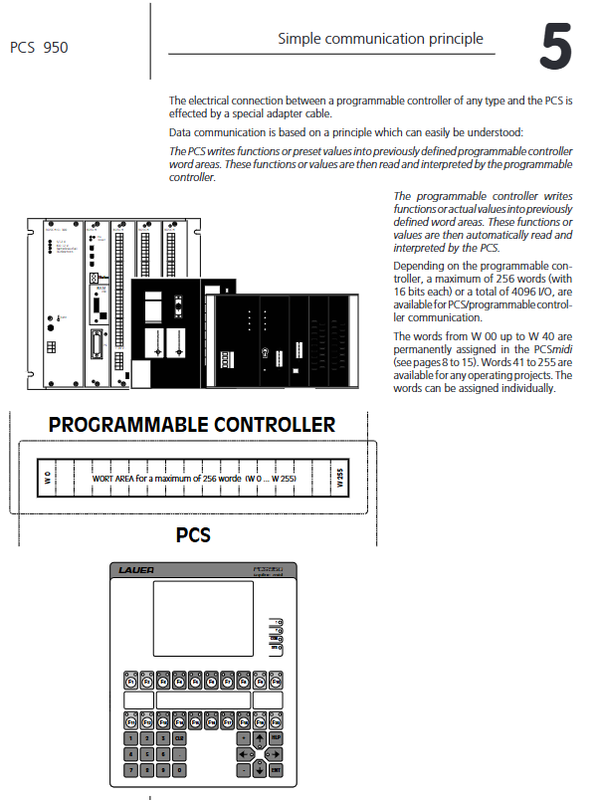
PCS950 and PLC exchange data bidirectionally through up to 256 16 bit words W0-W255.
Partition: System Zone W0-W3; Status zone W4-W17; Command area W20-W40; Message area W41-W104; Variable area W110-W255. PLC write command word control panel; Panel feedback includes buttons, time, and internal status.
2.1 Priority System (8 levels in total, the higher the number, the higher the priority)
The panel can activate multiple priorities at the same time, but only display the highest valid priority. Some priorities can be blocked through the command word W36.
Priority Number Name Purpose
0 Idle idle page standby screen, default display when powered on
1. Operating page parameter input and operation screen (operation text 1-127)
2 Information Information General Information Message
3 Warning Warning Warning Messages
4 Failure Device Failure Messages
5 History Log History Message Browsing
6 RecipeManager Recipe (Reserved) Recipe Management, manual marked in preparation under development
7 Comm Error Communication Error PLC communication disconnection automatically pops up
8 Offline Menu: Press the HELP+CLR button to access the offline menu, disconnect PLC communication, and use it to copy firmware records from the storage card
Priority can be masked through the W36 command bit, for example, to prevent the operation screen from being interrupted by an alarm during runtime.
2.2 Text Page Types
Idle texts (128): Priority 0 standby screen.
Operating texts (127): Priority 1, used for parameter modification input. Each page can be assigned an access password level.
Message texts (1024 pieces): Bind PLC message bits, information/warning/fault, up to two lines. Supports 5 clearing confirmation strategies: PLC reset clearing/panel CLR button reset/conditional confirmation, etc.
History texts: The log buffer stores the occurrence of COME, disappearance of GONE, and confirmation of ACK time for messages, and is cyclically cached.
Printer texts for printing text: message printing, job report printing.
Help texts: Press the HLP key to bring up, each page can be bound with independent help, up to 32 lines.
2.3 Variable System
Divided into external variables (from PLC W110-W255) and internal predefined variables (83, time date, counter, print control, log information). Variables are divided into three categories:
Actual value: only displayed, panel cannot be edited;
Preset setting value: The panel can be modified and written to the PLC;
Preset-P protected setting value: requires corresponding access permission level to allow modification.
All external variable formats
Variable type description
BIT bit variable PLC single bit, text mapping 0/1 two descriptions, modify and immediately write to PLC
STRING/CSTRING string: One byte corresponds to a text description; CSTRING writes to PLC immediately after each modification; STRING confirms ENTER and writes
BCD-1/BCD-2 BCD encoded digits (16 bits/32 bits), decimal display, no decimal point
BIN-1/BIN-2 unsigned binary, supports scaling and decimal point; Calculator input mode/Shift input two editing modes
VBIN-1/VBIN-2 signed binary numerical values
WORD word variables edit 16 bit characters bit by bit; Supports binary, hexadecimal, and decimal display
ASCII characters ASCII string, up to 32 characters long
TIMER timer BCD hour minute second timer, used for internal 8-channel timers
Each line of the screen can hold up to 8 variables.
2.4 Password Access Permissions
0-9 has a total of 10 access levels, with a 4-digit password set for each level. Binding access level for operation page; The Preset-P variable can only be modified if the current login level is ≥ page level; Soft key 256=LOGIN login; 257=Logout logs out and returns to level 0. Enter the wrong password three times in a row to lock the login dialog box.
2.5 Alarm message and log function
Monitor up to 1024 PLC message bits; Assign priority (information/warning/fault) and delete confirmation mode to each message;
Automatically record event time: COME event triggered, GONE event disappeared, ACK confirmation time;
Two independent loop buffers:
History buffer: displays up to 128 historical records, FIFO/LIFO first in first out/last in first out;
Message printer print buffer: used for report printing;
You can print shift and work order reports at any time, and print internal/external variables.
2.6 Internal Timer
8 independent timers, each timer supports 8 sets of daily cycle switch times (hour minute second); The timer output status is transmitted back to the PLC in bytes. Support cross midnight timing.
2.7 Printing function (PRN port)
Two printing modes:
Operating printer operation printing: The PLC issues a text number and immediately outputs it for printing;
Message printer: Print log buffer messages; Supports XON/XOFF, RTS/CTS handshake protocols. Can print control characters such as TAB, page change FF, line break LF, etc.
2.8 Real time clock, running hour counter
Real time clock: year/month/day/week/hour/minute/second; Can be modified on the panel or synchronized with PLC for time; Save in non-volatile RAM.
Running hour counter: power down saving; It can be read from internal variables or manually corrected.
2.9 Soft key
20 F1-F20 function keys, supporting two types of actions:
External soft key action: triggers read and write operations on PLC words, up to 255 characters;
Internal soft key actions: 256 login to LOGIN, 257 logout to LOGOUT; The function of each F key can be dynamically changed based on the current display page (priority).
When the button is pressed, the corresponding position will be set to 1 and output to the PLC (W4-W5 status word).
2.10 PLC Communication Word Mapping (Key)
W0-W3 system area: for internal use within W0-W2; W3 communication fault word;
W4-W8 key status area: W4/W5 returns F1-F20, CLR, ENT, directional keys and other key bits; W9-W12 returns BCD format date and time;
W13-W17 panel status area: log, print cache count, current display priority, text number;
W20-W27 LED control word: controls the green and yellow LEDs of F1-F20 to stay on and flash;
W34-W40 Command Word (PLC Write):
W34: Work area bitmap number;
W35: Status page number+soft key line number;
W36: Total priority enable, communication disable, clock synchronization, alarm output and other overall control bits;
W37: Printing control, message block transmission, LED shielding;
W38: Idle text number, operation page number;
W39: Printing task/pointer adjustment;
W40: Operate to print text numbers;
W41-W104 message block area: corresponding to 1024 alarm message bits;
W105-W109 retains extensions; W110-W255 user variable area.
Attention: The key status words and panel status words are not synchronized with the PLC receiving and variable refreshing; We cannot guarantee that all communication cycles will be consistent, and the PLC program needs to perform consistency processing.
Important maintenance and troubleshooting points
Battery maintenance: Backup RAM battery PCS010, it is recommended to replace it every 5 years; The replacement must keep the device powered on to prevent loss of historical logs.
Polyester film on the front surface is prone to static electricity and can only be wiped with a damp cloth; Explosion proof models are particularly strictly followed. Do not touch toxic substances inside the damaged LCD screen.
Communication fault COM flashing: Check DIP switch, cable, PLC driver version, refer to the corresponding PLC driver manual for PCS9.xxx.
Offline menu HELP+CLR: Used to copy firmware/screen records to a memory card, execution will disconnect PLC communication.
Expansion cards and PCS891 keyboards must be powered off and plugged in, and hot plugging is strictly prohibited.
Configuration can only use PCSPROWIN software, other tools may cause panel and PLC abnormalities.