KUKA Robots KR CYBERTECH nano-2 Assembly Instructions
KR 6 R1840-2, KR 8 R1640-2, KR 10 R1440-2, three 6-axis small serial robots; Support installation at any tilt angle for ground, wall, and ceiling, compatible with controller KR C5 micro and KR C5 S. The manual includes complete product instructions, safety, technical parameters of the entire model, project planning, transportation, installation and operation, maintenance, repair, storage and disposal, options, and appendices for complete body assembly and maintenance information.
Product Description
Robot system composition: robotic arm body, controller, power/data cables, teaching pendant, software, tools and options.
Mechanical arm body structure: 6-axis articulated robot, assembly including straight wrist inline wrist, linkage arm, rotating column, base frame, and complete electrical wiring.
A1-A5 is equipped with mechanical terminal hard blocks, which are only used for equipment protection and cannot protect personnel; Personnel protection relies on the SafeRobot safety function of the controller, or by selecting the A1-A3 adjustable mechanical shaft limit.
Straight wrist: A4-A6 integrated wrist; A5 adopts synchronous belt transmission; The wrist flange complies with ISO 9409-1 standard.
The rear of the base is equipped with an A1 interface, which integrates a micro RDC cool unit; All motors and signal cables use quick plug connectors; The electrical wiring harness is divided into A1-A3 cable components and A4-A6 cable components.
Permitted use and prohibited misuse
✅ Allow: handling, assembly, and workpiece handling; It is necessary to comply with environmental conditions and maintenance cycles.
❌ Prohibited: climbing, carrying people and animals, outdoor activities, explosion-proof areas, radioactive activities, and underground operations; Unauthorized use will result in the loss of warranty.
Robots belong to partially completed machinery and cannot be put into operation independently; The system integrator completes the entire system, issues an EC conformity declaration, and affixes the CE mark.
Available options: Release device for brake release, transport fork groove, lifting ring, A1-A3 mechanical shaft limit, pipeline package, cascading RDC module.
Technical Data
Basic Overview of Three Models
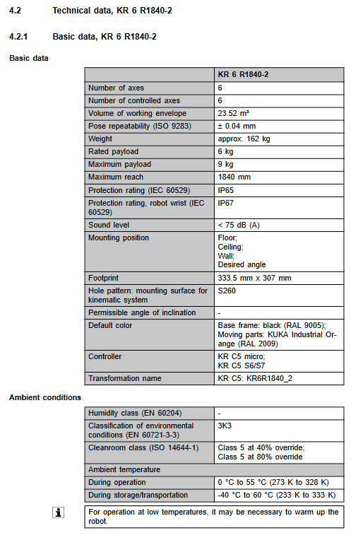
Parameters KR 6 R1840-2 KR 8 R1640-2 KR 10 R1440-2
Number of axes: 6-axis fully controlled 6-axis fully controlled 6-axis fully controlled
Rated load 6 kg 8 kg 10 kg
Maximum load 9 kg 12 kg 14.3 kg
Maximum reach distance 1840 mm 1640 mm 1440 mm
Repetitive positioning accuracy ISO 9283 ± 0.04 mm ± 0.04 mm ± 0.04 mm
The self weight of the body is about 162 kg, about 158 kg, and about 153 kg
Protection level body IP65, wrist IP67 body IP65, wrist IP67 body IP65, wrist IP67
Noise<75 dB (A)<75 dB (A)<75 dB (A)<75 dB (A)
Installation method: Ground, wall mounted, suspended ceiling, floor, wall mounted, suspended ceiling at any angle, floor, wall mounted, suspended ceiling at any angle, any angle
Operating temperature range of 0-55 ℃; Storage -40~60 ℃ Operating at 0-55 ℃; Storage -40~60 ℃ Operating at 0-55 ℃; Storage -40~60 ℃
Compatible controller KR C5 micro/KR C5 S KR C5 micro/KR C5 S KR C5 micro/KR C5 S
Axis parameters: Range of motion for each axis of each model, maximum axis speed, Mastering zero position; Tilt installation will limit the range of motion of the A1 axis, and the actual installation tilt angle must be filled in the WorkVisual software, otherwise overload and accidental motion may damage the robot; The manual includes a curve diagram of the A1 axis under different controllers and a two-dimensional drawing of the working envelope.
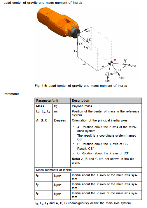
Load chapter: Wrist flange ZH series (ISO 9409-1); Load center of gravity, moment of inertia, load curve diagram; Distinguish between normal operation and emergency stop conditions, flange bearing axial force, radial force, overturning moment, and torsional moment; Provide installation hole drawings and allowable additional load values for the boom, link arm, and rotating column.
Base load: Output vertical force, horizontal force, overturning moment, and A1 torque for ground, ceiling, and wall mounted working conditions respectively; The structural verification must take the maximum value of the emergency stop condition to prevent overturning and falling.
Cable parameters: distinguish between KR-C5-micro and KR-C5-S cable sets; The optional length of the cable is 1-50 meters, and the minimum bending radius is specified; It is necessary to independently protect the grounding; Complete interface pin diagram of A1 base.
Stop distance and stop time: distinguish between STOP0 cutting off the brake and STOP1 safe stop; For all models, provide A1-A3 stop angle and stop time charts for KR C5 micro and KR C5 S according to different arm extension ratios (33%/66%/100%), program magnification POV, and different loads; The brake will wear out, it is recommended to conduct an annual on-site review of the actual stopping distance.
Refer to KUKA Xpert for the body nameplate label and REACH regulation information.
Planning and Design
Reminder for accelerated wear conditions: long-term temperature limit operation, corrosive dust environment, continuous performance limit, single axis high duty cycle, monotonic reciprocating short stroke, wrist long-term static, external process force; Consult KUKA for the above working conditions to shorten the maintenance cycle; The body comes with overheating and overload monitoring, and automatically shuts down when exceeding the limit.
Two base schemes
Centering option base: concrete floor; Concrete grade C20/25; Bottom plate, chemical anchor bolt, positioning pin; It is prohibited to add a soundproof leveling layer between the base and concrete.
Rack mounted installation: customer steel structure, KUKA linear slide table; Positioning pin+high-strength bolt; The installation requires strict requirements for flatness, roughness, and structural stiffness.
Cable planning: minimum bending radius for motor cables and data cables; Power cables and signal cables are laid separately in metal cable trays to ensure EMC electromagnetic compatibility; Double protection grounding; Cable layout eliminates tripping risks; Cables are prohibited from withstanding tensile forces.
A1 Base Interface Definition: Motor XD30, Data XF31, Mastering Calibration Interface Drawing.
Transportation
Each model is required to have an exclusive mandatory transportation posture, which must be maintained throughout the transportation process. It is prohibited to change the posture before fixing it to the base to prevent tipping.
Transportation method: Supports forklift fork slots (optional) and crane lifting rings for hoisting; Hanging point location drawing; Avoid impact and vibration during transportation; Dismantle the lifting ring/fork groove in place; Provide the overall dimensions and center of gravity position for the transportation of the entire machine.
Startup Debugging and Restarting
The complete process of covering the installation of fixed base floor and rack mounted floor/wall/ceiling, distinguishing the wiring differences between KR C5 micro and KR C5 S.
Prerequisite: The robot is in a transport position, the base steel structure is completed, and the lifting equipment is in place.
General installation steps
Lift into place and install the positioning pin;
Tighten the bolts diagonally in multiple stages to the specified torque;
Connect dual protection grounding;
Connect motor cables and data cables; A click on the connector indicates locking; Distinguish between KR-C5-micro and KR-C5-S wiring;
Fill in the actual installation posture and inclination angle of the robot using WorkVisual software;
Install tools, power on, jog in T1 mode, perform axis Mastering zero calibration, and perform overall functional testing.
After 100 hours of operation, all anchor bolt torques must be rechecked.
Provide a complete schematic diagram of the wiring of KR C5 micro and KR C5 S motor cables, data cables, and grounding cable pins.
Maintenance
Only allow maintenance projects recorded in the manual to be executed; The remaining repairs will be entrusted to KUKA authorized personnel; Emergency stop, lock and power off before maintenance; The maintenance cycle is shortened when the operating oil temperature exceeds 60 ℃; This series of robots does not have a hydraulic nitrogen balance cylinder.
Maintenance cycle summary table
Periodic homework content consumables
After being put into operation, only one 100 hour recheck of the torque of all bolts on the base will be conducted
5000 hours visual inspection of A1 flexible pipeline package for damage –
Apply lubricating grease PETAMO GHY 133 N to the 10000 h A1 cable package
20000 hours or at the latest 5 years for A1-A3 gearbox oil change; Replace A5 synchronous belt Optigear Synt. ALR-150 gear oil; Synchronous belt, tensioning tool TSM alpha 2
Suggest KUKA to conduct a comprehensive on-site inspection of the entire machine after 7 years or changes in operating conditions.
Key maintenance process
A1 cable package lubrication: Remove the base cover plate, visually inspect the corrugated tube, apply lubricating grease with a brush, restore the cover plate, and jog A1 to evenly distribute the grease.
A5 synchronous belt replacement
Return the wrist to zero and remove the wrist side cover plate; Disassemble the M4 screws step by step, and do not remove them all at once to prevent the A5 motor from falling;
Replace the synchronous belt and use the TSM alpha 2 frequency meter to set the tension frequency to 130 ± 5 Hz;
Apply sealant to the sealing surface and restore the cover plate; Complete A5 axis Mastering zero calibration.
Gearbox oil change (A1/A2/A3)
The gearbox is at operating temperature; Measure the actual amount of oil released during oil discharge; The gearbox must be flushed if the oil release rate is less than 70% of the rated value; Rinse twice with less than 50%, and move the entire stroke during rinsing; Magnetic plug inspection for metal debris; Tighten the plug according to the specified torque; Oil change completed T1 mode jog operation, check for leaks.
Robot cleaning: Prohibit high-pressure water guns and direct blowing of compressed air on bearing seals; Use water-soluble neutral cleaning agents; Power off operation to prevent liquid from entering the electrical chamber.
Maintenance
The manual describes the key points for replacing the A1-A6 motor and disassembling the A1-A3/A4-A6 wiring harness.
General safety for motor replacement: power off, lock the main switch, wait for 5 minutes for high voltage discharge; Before disassembling the motor, the corresponding shaft must be mechanically locked to prevent the arm from accidentally falling;
Motor installation: Check that the gradual flowering key is not damaged and apply the corresponding lubricating grease evenly; The O-ring seal must be replaced if it is damaged; Tighten the bolts diagonally in steps; After installation, the axis must undergo Mastering zero calibration and T1 mode trial operation.
Overview of Electrical Wiring; Repairs must use KUKA original spare parts; Complete verification of all safety functions after maintenance is completed.
Suspension, Storage, and Disposal
Shutdown disassembly: The robot moves to the designated transport posture; Install lifting rings and slings; Disconnect all cables; Lift the crane off the main body.
Storage: Maintain transportation posture, clean the robot, provide rust prevention protection, and meet temperature and humidity storage conditions.
Scrap disposal: Lubricating oil, electronic components, and metal structures should be classified and disposed of according to local environmental regulations.
Options
Release device: manual movement of the robotic arm in power-off state; Provide a complete explanation of the installation process and safety constraints for a non actuated mobile robotic arm.
Fork groove transportation components, lifting rings, A1-A3 mechanical shaft limit, pipeline package, and cascading RDC module.