KUKA MA KR SCARA X Installation Guide
KUKA SCARA planar four axis robot mechanical body assembly manual, compatible controller KR CS Box-2; The product belongs to incomplete machinery (semi-finished product), and the responsibility for CE, risk assessment, and safety integration of the entire machine belongs entirely to the system integrator.
Technical Data
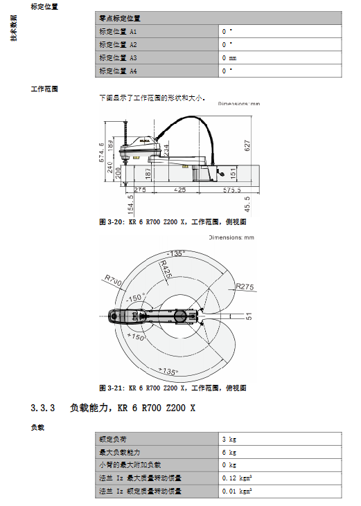
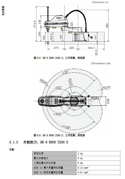
Contains basic parameters, axis parameters, load capacity, foundation load, stopping distance time, and REACH information for 6 models.
Overview of Basic Models
Model: Rated Load, Maximum Load, Maximum Reach, Z Stroke, Body Weight, Repetitive Positioning Accuracy, XY Repetitive Positioning, Z Repetitive Positioning, R
KR6 R500 Z200 X 3 kg 6 kg 500 mm 200 mm Approximately 17.3 kg ± 0.02 mm ± 0.01 mm ± 0.01 °
KR6 R600 Z200 X 3 kg 6 kg 600 mm 200 mm Approximately 18.25 kg ± 0.02 mm ± 0.01 mm ± 0.01 °
KR6 R700 Z200 X 3 kg 6 kg 700 mm 200 mm ‑ ±0.02 mm ±0.01 mm ±0.01°
KR10 R600 Z300 X 5 kg 10 kg 600 mm 300 mm ‑ ±0.02 mm ±0.01 mm ±0.01°
KR10 R700 Z300 X 5 kg 10 kg 700 mm 300 mm ‑ ±0.02 mm ±0.01 mm ±0.01°
KR10 R800 Z300 X 5 kg 10 kg 800 mm 300 mm ‑ ±0.02 mm ±0.01 mm ±0.01°
Protection level IP20; Noise<75 dB (A); Only installed on the ground.
Environmental conditions: Operating at 0~45 ℃; Storage -25~55 ℃; Environmental level 3K22.
Controller: KR CS Box-2.
Load critical rules
It is necessary to verify the load mass+center of gravity Lx/Ly/Lz+moment of inertia Iz simultaneously, using the KUKA. Load tool for verification; Load data must be entered into the controller, otherwise the gear motor will be damaged due to overload.
The forearm supports the installation of additional loads with a maximum weight limit, which will reduce the robot’s rhythm.
The output force and torque of the flange are divided into normal operating conditions and emergency stop peak operating conditions; All values do not include safety factors, and additional safety factors must be added to the fixtures.
Foundation load
Output vertical force Fv, horizontal force Fh, overturning moment Mk, A1 turning torque Mr; the values do not include safety factors, and the design of civil foundation must include safety factors; The weight of the additional load needs to be manually included in the vertical load.
Stop distance and stop time
Distinguish between Stop0 and Stop1; The stopping stroke of multi axis compound motion will increase.
The data is the reference value tested under POV=100% rated/maximum load conditions; Suggest stopping the trip for on-site verification every year.
REACH regulation
Information on SVHC substances of high concern can be accessed through the KUKA Xpert system.
Planning
Foundation fixing device: self provided by the user, with a flat base surface; Strictly follow the installation hole drawings; Ensure resistance to overturning.
Connecting cables and interfaces: motor cables, encoder data cables, equipotential grounding wires; Specify cable length and plug pin definitions.
Important constraints on user cable routing
Prohibit binding user cables to robot bellows;
Use high flexibility shielded cables to ensure reliable grounding of the system;
User cables must not interfere with the movement of the robot’s main cable;
Reserve installation screw holes (M4) for user cable brackets on the forearm and base, and provide installation drawings.
Transportation
The standard transportation posture must be specified in the document, and all external cables must be disconnected.
Transportation method: Forklift transport packaging box; Small models support manual handling by two people; Provide a table of transportation dimensions for each model.
Handling warning: Adequate rated lifting and handling equipment must be used to prevent falls.
Putting into Operation and Restarting
Installation process of ground robots
Preparation tools: torque wrench, hexagon socket tool; The user shall prepare the foundation fixing components themselves.
Positioning and leveling of the base; Lift the robotic arm, position it, and tighten the bolts diagonally step by step.
Connect the motor cable, encoder data line, and equipotential grounding wire in sequence, and the plug must be locked tightly.
Cable documentation: complete pin definitions for motor cables, X31 encoder data cables, and assembly drawings for grounding components.
Two ways to manually move the robotic arm
A1/A2 axis: T1 mode, KUKA. ControlStudio activates servo free mode and releases the brake to manually move.
A3/A4 axis: T1 mode, press the brake release button on the side of the body to manually move; ⚠️ There is a risk of the brake load falling off when releasing the A3 vertical Z-axis, and the load must be manually lifted.
Pre operation checklist: no condensation, no collision damage, grounding continuity, and all functional tests of safety devices.
Maintenance
Power off, lock and tag before maintenance; After all maintenance is completed, retest the security functions.
Periodic maintenance project consumables
Check the torque of the fixing bolts on the base for 100 hours (only performed once during the first operation)
1500 h A3 ball spline screw lubrication General duty Li Base Grease No.2 (approximately 5 g)
The replacement of A3/A4 toothed belts within 4000 hours or at the latest 1 year must be carried out by authorized personnel from KUKA
Replace the main battery pack within one year
1 year re inspection of the torque of the fixed bolts on the base –
Maintenance
The manual only describes the prerequisites for disassembly and assembly; Key maintenance operations such as the replacement of A3/A4 toothed belts must be carried out by authorized and qualified personnel from KUKA.
Suspension, Storage, and Disposal
Shutdown and disassembly steps: the robot switches to the transport posture; Disconnect all cables; Loosen the base bolts and lift off the body.
Long term storage: Sealed interface, stored in a compliant temperature and humidity environment.
Scrap: Electrical components and batteries should be classified and disposed of according to local regulations.