KUKA KR C4 Smallsize-2 family’s smallest control cabinet
KR C4 smallsize-2 is the smallest control cabinet in the KUKA KR C4 family, belonging to the small robot dedicated controller (CCU_SR small robot control unit), supporting up to 8 axes, suitable for lightweight small robotic arms, and also supporting CK customer customized kinematics; Stackable installation, compact size. For engineers with backgrounds in electrical engineering, robotics, and Windows, it is recommended to participate in KUKA’s official training.
Purpose
Target audience: System integrators, debugging and maintenance personnel;
Designated use: Drive KUKA small robotic arms, linear units, positioners, CK custom mechanisms that comply with ISO10218-1;
Prohibited scenarios: trampling on cabinets, operating beyond specifications, explosion-proof environment, underground mining.
Product Description
Complete system: small robotic arm+KR C4 smallsize-2 control cabinet+smartPAD teaching pendant+cables+KSS software+options.
Core hardware unit
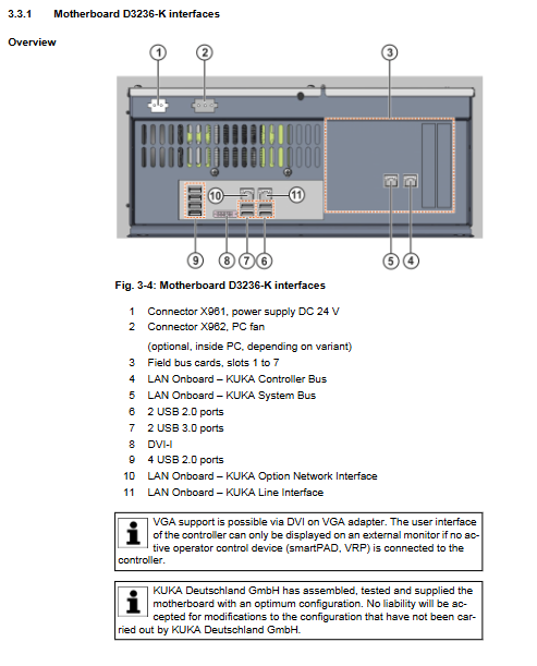
KPC control PC, supporting D3236-K and D3445-K motherboards; Responsible for human-machine interface, program editing, path planning, driver control, communication, and security monitoring.
Drive Configuration (DC), consisting of KPP_SR400 (power pack) and KSP_SR (servo pack); Generate DC intermediate circuit voltage, motor and brake control, and brake mode voltage monitoring.
CCU_SR Small Robot Cabinet Control Unit (CIB_SR+PMB_SR): complete machine power distribution, internal bus communication, 9-way safety input, 4-way floating safety output, fan/temperature monitoring, main contactor control, Mastering origin test; 6-way high-speed measurement input; Power outage relies on backup battery storage location and controlled shutdown, load testing battery health status.
RDC rotary digital converter: collects motor rotary position and motor temperature; EDS memory storage origin configuration; The length difference of cables in each channel of RDC shall not exceed 10 meters.
CSP controller system panel: status LED, USB, KLI upper communication port, KSI service network port.
Low voltage power supply unit, backup battery pack, power filter; Optional transient suppressor (surge protection module).
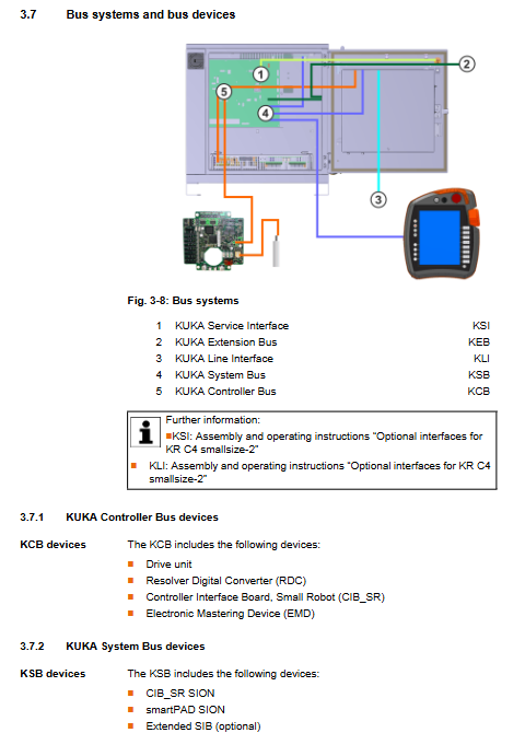
Three major buses
KCB controller bus: driver unit, RDC, CIB_SR, EMD electronic calibration unit;
KSB safety bus: CIB_SR-SION, smartPAD SION, optional Extended SIB;
KEB expansion bus: EtherCAT, IO modules, various fieldbus options.
Interface key constraint: Choose between discrete safety interface X11 and Ethernet safety interface X66 (PROFIsafe/CIP Safety), they cannot be enabled simultaneously.
Cooling architecture: dual loop cooling; The internal control electronic components are cooled by a PC fan through a heat exchanger; The external fan directly dissipates heat to the braking resistor, low-voltage power supply, and drive unit radiator; It is prohibited to install filter cotton on the ventilation opening, as it may overheat and shorten the lifespan of the device.
Optional accessories: smartPAD bracket; Roller kit, only for short distance movement within the cabinet group, prohibits long-distance dragging, vehicle towing, and tipping risks; The TS35DIN rail on the right side of the cabinet is used for customers to install third-party components.
Mechanical features: Supports stacking, up to 2 smallsize-2 controllers can be stacked; It can also be combined with a smallsize drive box.
Technical Data
Mechanical parameters: overall dimensions of the machine, M8 mounting holes for ground installation, and openings for technical cabinets; Cabinet door opening angle; Install minimum clearance;
Environmental conditions: working temperature+5~+45 ℃; Storage -25~+70 ℃; When the altitude is greater than 1000 meters, the power will decrease by 5% for every 1000 meters increase; Resistance to vibration and impact; The overall weight and noise of the machine are less than 66dB (A);
Electrical parameters: power supply specifications; External PELV-24V power supply; The smartPAD cable can be extended in up to two sections, with a total length of ≤ 50 meters;
Electrical parameters of SIB safety board: input/output threshold, dynamic test output load, maximum cable length; Safety performance EN ISO13849-1 Cat.3/PL d, PFH failure rate data;
Warning label on nameplate: The maximum residual voltage in the intermediate circuit is 780 VDC, and it is necessary to wait for discharge after power failure; The nameplate is strictly prohibited from being painted or removed;
REACH SVHC Substance Description.
Security (Core Chapter)
EC Machinery Directive; Robots belong to “partially completed machinery”; The system integrator is responsible for the risk assessment of the entire machine; Unauthorized modification of software and hardware results in loss of warranty.
Personnel classification: system integrator, maintenance personnel, operator, all personnel must read the safety chapter.
Definition of danger zone: robot workspace+braking stop distance; Stop distance testing with actual tool load. After running the equipment in a hot state for about 1 hour, test and take the worst-case scenario result.
Stop category
STOP 0: Immediately cut off the power supply to the drive and brake;
STOP1: Controller controlled deceleration shutdown, cutting off the drive after shutdown;
STOP1-DRS path oriented braking;
STOP2: Keep the drive powered on and monitor the Safe Operational Stop after shutdown.
Four operating modes
Mode description
T1 manual deceleration, Cartesian maximum 250 mm/s, teach programming
T2 manual high-speed,>250 mm/s, prohibit teaching programming
AUT control cabinet local automatic mode
AUT-EXT upper PLC external control automatic mode
Switching modes during operation triggers STOP2.
Safety devices
Emergency stop; Three level enable switch (middle position allows movement; fully press → STOP1; Release → STOP2); Enable the switch to undergo a complete functional test at least once a year.
External emergency stop must be configured to prevent the loss of emergency stop protection after unplugging the teaching pendant; External safety door, external enable input.
T1 mode speed monitoring: axis speed+Cartesian flange speed monitoring.
Multiple protections: jog Jog, software limit, mechanical hard limit; Manually moving the robotic arm without driving energy is only for rescue purposes and may damage the motor brake. After the test, the brake function will be tested.
Start up mode: If external security protection is not ready, T1 jog is allowed; Shielding external security protection, only for debugging and troubleshooting, personnel are strictly prohibited in hazardous areas; There are differences in behavior among different versions of KSS; The startup mode is disabled when there is an upper level connection in the Ethernet security interface.
SPOC single point control principle: Submit interpreter PLC、OPC、 Remote tools and WorkVisual online configuration must be securely constrained to prevent background rewriting of variables that may cause unexpected movements.
Safety points for various working conditions
IT Security: It is recommended to deploy information security management;
Debugging: Change default password; After modifying the machine data, provide the TCP, palletizing robot, and decoupling coupling axis practical verification testing process;
Manual mode: New/modified programs prioritize T1 low-speed testing; Multiple people entering the protective zone, each person independently activating the device;
Maintenance: Power off and lock the entire machine; High voltage in the intermediate circuit, power off and wait for at least 5 minutes for discharge; Strict ESD anti-static measures; Some components remain live even after power failure;
Hydraulic/pneumatic balance cylinder belongs to pressure equipment and follows pressure equipment instructions;
Scrap storage follows local regulations.
Quoting the complete list of EU/international standards.
Planning and Design (Pre integration)
EMC electromagnetic compatibility: external cable shielding, shielding layer extensively crimped with PE bars; The control cabinet belongs to Class A industrial equipment.
Installation conditions: floor standing, side by side, stacked; Adhere to the minimum maintenance gap.
PE equipotential mandatory requirement: 4mm ² equipotential cable between the robotic arm and the control cabinet; Control cabinet body to distribution cabinet PE row 4 mm ²; When paired with an external drive box, the drive box needs to be grounded at 16mm ².
Motor interface X20: Han Yellock connector, pin definition, suitable for small robot body axis.
X11 Discrete Security Interface
Dual channel dynamic pulse test TA-A/TA-B;
External emergency stop, safety door, external enable switch;
Provide complete schematic diagram: external emergency stop, safety door wiring, floating contact safety input/output;
The safety gate must be equipped with a confirmation button outside the fence, and automatic reset and operation are prohibited when the door is closed; Dynamic testing timing diagram.
X66 Ethernet safety interface (PROFIsafe/CIP Safety), SafeOperation option; Definition of input and output byte bits; Suggest writing 1 for reserved bits to avoid unexpected downtime.
CIB_SR board EtherCAT interface X44/X65.
Scenario and operating steps for verifying the function of the USS 2 load voltage contactor.
Hardware change rules: To replace a hard drive, board, or add or remove axis peripherals, the WorkVisual software must reconfigure the system.
Transportation
Three transportation methods: lifting with lifting rings, pallet handling, and optional rollers;
The roller kit is only used for short movement inside the cabinet group, and it is strictly prohibited for vehicles to drag and transport it, as there is a risk of tipping over;
Transportation prerequisites: power outage, all cables removed, cabinet doors closed, and placed upright; Hang rings with 4 × M8 lifting ears, with standardized lifting angle, and incorrect oblique lifting is prohibited.
Startup and Re Debugging
Complete power on process:
Visually inspect the robotic arm and control cabinet to confirm that there is no condensation inside the cabinet;
Install the control cabinet in place and adhere to maintenance clearances;
Laying motor cables and X21 RDC data cables; Separate the wiring of motor cables and data cables; Comply with cable bending radius (fixed laying 3-5 x wire diameter; drag chain 7-10 x wire diameter); Replacing the RDC data cable requires re Mastering the origin calibration;
Install the smartPAD bracket and plug in the teaching pendant;
Connect PE equipotential;
Harting X1 connected to the main power supply;
Restore battery discharge protection plug;
Plug in configuration X11 or X66 safety interface in power-off state;
After hardware modifications, WorkVisual completes the system engineering configuration; Enable Start up startup mode as needed;
Clear the dangerous area of personnel and objects, release the emergency stop, and turn on the power.
Equipment Operation
Explain the smartPAD teaching pendant: front buttons (mode knob, emergency stop, space mouse, jog, start stop, override, menu); Three level enable switch and USB interface on the back.
Unplug the teaching pendant and the machine’s emergency stop fails; Reconnect and wait for about 30 seconds. The emergency stop and three gear enable switches must be retested; The removed teaching pendant should be moved out of the work area to prevent mixing.
Maintenance
Maintenance of safety prerequisites: power off and lock, disconnect the incoming power supply; Wait for the intermediate circuit to discharge for 5 minutes; ESD anti-static; Do not blow compressed air directly into the cabinet.
maintenance cycle
Annual: Complete inspection of CCU_SR relay output function; All emergency stop and enable switch function tests; Clean the fan grille;
Every 2 years: Clean the radiator and drive cooling fins; Cleaning of the entire machine casing;
Three shift operation for 5 years: motherboard button battery replacement; Replacement of PC fan and external fan;
Battery monitoring alarm, replace battery packs in pairs.
Maintenance work: CCU_SR relay output testing (local emergency stop, operator safety confirmation, peripheral enable output); Complete machine cleaning; After maintenance, check the wear of fuses, plugs, grounding, and cables.
Maintenance and Replacement
Maintenance can only use KUKA original spare parts; High strength 10.9 screws must be replaced after disassembly and must not be reused. Each component includes safety prerequisites, tool list, step-by-step disassembly and assembly, connector definition, and functional testing after replacement. List of replaceable parts:
External fan;
Complete driving unit (KPP_SR+KSP_SR);
Replace the drive unit and wait for the intermediate circuit to discharge for 5 minutes. The heat sink should be high-temperature to prevent burns;
KPC complete set, PC fan, motherboard button battery, SSD solid state drive; After replacing the SSD, WorkVisual must reconfigure the system or restore the image;
CCU_SR small robot control unit; Pay attention to the unlocking mechanism of the connector during disassembly and assembly, and forcefully plug and unplug to damage the connector;
The battery pack must be replaced in pairs, with strict attention to polarity to prevent short circuits; The battery does not have a built-in fuse, and a short circuit can generate a significant short-circuit current;
Low voltage power supply unit; Power filter; Braking resistor;
Installation of KSS system software.
Troubleshooting
CCU_SR board complete set of LED indicator lights: power supply, bus, safety node, fuse LED; Corresponding fault phenomena and solutions for different color flashing frequencies;
CCU_SR fuse number, rated current, and purpose;
CSP system panel LED; Main board network port Link Activity indicator light;
Card fault handling: Check wiring, disconnect peripherals, restart testing; Replace the CCU_SR module despite the malfunction.
Shutdown, Storage, and Scrap Disposal
Shutdown and return: Disconnect all external motor cables and grounding wires, and prepare for transportation;
Long term storage: indoor dry and dustproof, no condensation; Remove the battery and seal the interface casing for protection;
Scrap and disassembly: classified by material; Waste batteries and hazardous materials should be returned to suppliers for recycling, and the disposal of household waste is prohibited.