Assembly/Installation Manual for KUKA KR C4 Compact Control Cabinet
This is the assembly/installation manual for the KR C4 compact control cabinet, focusing on hardware installation, wiring, planning, and power on debugging, which is different from the BA series operation manual (which focuses on operation, maintenance, and troubleshooting); The hardware platform CCU_SR supports up to 6 axes and 19 inch rack installation. It runs KSS industrial robot software and is designed for system integration engineers with professional backgrounds in electrical, robotics, and Windows.
Product Description
Complete set of robots: robotic arm+KR C4 compact control cabinet+smartPAD teaching pendant+cables+KSS software+options. The control cabinet is divided into two main units: Control box and Drive box, which support independent floor standing or 19 inch rack installation.
Core Hardware
KPC Control PC: The motherboard supports D3076-K/D3236-K/D3445-K; Responsible for HMI, program processing, path planning, driver control, and safety monitoring.
CCU_SR Small Robot Cabinet Control Unit (CIB_SR+PMB_SR): Whole machine power distribution, internal bus; 9 safety inputs, 4 floating safety relay outputs; Fan temperature monitoring, Mastering test input; Power outage relies on backup battery to store location and controlled shutdown; Load test battery health status.
Drive box (KPP_SR power package+KSP_SR servo package): generates intermediate circuit DC voltage, motor/brake control, and brake mode voltage monitoring; Integrated braking resistor and fan.
Low voltage power supply unit, backup battery pack, power filter, EDS electronic data storage card.
Interface Overview (Important Constraints)
X11: Discrete 50-D-Sub security interface; X66: Ethernet safety interface (PROFIsafe/CIP Safety); Choose one of the two and do not use them simultaneously.
X19: Teaching pendant; X20: Motor connector; X21: RDC data of robotic arm; X65 EtherCAT; X69 KSI service port.
Cooling system: dual fan ambient air cooling; It is prohibited to install filter cotton on the ventilation opening, as it may overheat and shorten the lifespan of the device.
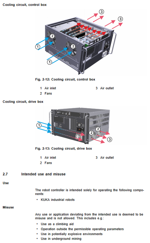
Designated use and prohibition of misuse
Drive KUKA small industrial robots;
Prohibit climbing and trampling, operating beyond parameters, explosion-proof environment, and underground mining.
Technical Data
Mechanical parameters: 19 inch chassis; Weight 33 kg; Protection IP20; Noise level of 54 dB (A); Provide dimension drawings for the entire machine, handle bracket, and smartPAD installation bracket.
Electrical parameters: single-phase 200-230 V AC, ± 10%, 50/60 Hz; rated power 2 kVA; The maximum heat loss is 400 W; the fuse is 2 × 16A slow melting.
Environmental conditions: working+5~+45 ℃; Equipped with battery storage -25~+40 ℃; No battery -25~+70 ℃; When the altitude is greater than 1000 meters, the power will decrease by 5% for every 1000 meters increase; Pollution level 2.
CIB_SR safety board electrical characteristics: input OFF interval -3-5 V; ON interval 11-30 V; 5-11 V undefined transition zone; Dual channel dynamic test output TA-A/TA-B; Pulse t1=625 μ s, period t2=106 μ s; maximum cable length 50 μ m; relay output design life of 20 years, maximum 100000 switches.
Safety performance: EN ISO 13849-1 Cat.3/PL d, SIL2; PFH<1×10⁻⁷; All safety components must be tested annually.
SmartPAD parameters: 8.4-inch touch screen; The cable can be extended in up to two sections, with a total length not exceeding 50 meters.
Nameplate labels, REACH SVHC list of substances of high concern.
Planning and Design (Pre integration Hardware Planning, this chapter is the core of the assembly manual)
EMC electromagnetic compatibility: All external cables use shielded cables, and the shielding layer is extensively crimped with PE bars; The control cabinet belongs to Class A industrial equipment.
Installation conditions: Independent floor standing/19 inch rack installation; Rack depth ≥ 600 mm; left and right ventilation gap ≥ 70 mm; can only be connected to a grounded neutral power grid, non grounded neutral systems are prohibited.
PE equipotential mandatory requirement, meeting EN60601-1 grounding continuity test.
Power supply parameters, fuse selection, cable specifications.
X11 Discrete Security Interface (50 Chip D-Sub)
7-channel dual channel secure input; 4-channel floating safety relay output; Dynamic pulse testing;
Complete pin definition; Schematic diagram and timing diagram of input and output wiring for external emergency stop, safety door, and floating ground contact;
The safety door must be equipped with an external confirmation button to prohibit automatic reset and operation when closing the door; The test output can only supply power to the input of this board and cannot be connected to other loads externally.
X66 Ethernet Safety Interface (PROFIsafe/CIP Safety)
Complete input/output byte/bit definition; It is recommended to force write 1 for reserved bits to prevent unexpected shutdowns; Schematic diagram of enabling switch wiring; SafeOperation option description.
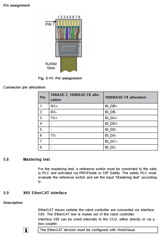
X65 EtherCAT; X69 KSI service debugging port.
Mastering origin calibration test interface description.
Hardware change rules: To replace a hard drive, board, or add or remove peripheral axles, the WorkVisual software must reconfigure the system.
Transportation
Transportation prerequisites: power outage, removal of all cables, closure of cabinet doors, and horizontal placement;
Transportation methods: pallet and forklift handling; Prohibit live transportation inside the cabinet, as vibration can cause board contact failure.
Startup and Debugging (Complete Steps for Assembly and Power on)
Visually inspect the entire machine, confirm that there is no damage during transportation, and that there is no condensation inside the control cabinet;
Install the control cabinet in place to ensure ventilation and maintenance clearance;
Wiring:
X20 motor connector: complete pin allocation, U/V/W for each axis motor, 24V/GND for brake, PE;
X21 RDC data cable pin definition; Separate the wiring of motor cables and data cables, and follow the bending radius; The length difference of cables in each channel of RDC is ≤ 10 m;
Plug in smartPAD teaching pendant X19; Unplug the teaching pendant and the local emergency stop will fail. The system must be connected to an external emergency stop;
Connect PE equipotential;
Restore battery discharge protection plug X305 (disconnected at the factory to prevent the transportation battery from being depleted);
Connect to the main power supply: distinguish between versions with mains-connectors and versions without connectors, with L/N/PE wiring color specifications;
Plug in safety interface X11 in power-off state (hot plugging is prohibited);
Download project configuration for WorkVisual after hardware modifications;
Clear the danger zone, release the emergency stop, close the switch and turn on the power;
Mandatory testing after power on: verification of a complete set of safety functions such as emergency stop, all enable switches, mode switches, and safety outputs.
Reconnect the teaching pendant and wait for about 30 seconds before retesting the emergency stop and enable switches.