KUKA KR C5 compactcab and KR C5 small-size cab cabinets
Assembly guide manual for KR C5 compactcab and KR C5 small-size cab cabinet with KR C5 slim-2 robot controller; Only describe the external cabinet, refer to the controller manual for instructions on the robot controller body; For engineering personnel with expertise in electrical and electronic engineering, it is recommended to attend KUKA College training; The copyright of the document belongs to KUKA, and unauthorized copying and disclosure are prohibited.
Product Description
The entire robot system consists of a robotic arm body, KR C5 slim-2 controller, cabinet body, teaching pendant, cables, software, and optional components.
Overview of two types of cabinet hardware
Cabinet structure: including cabinet door lock, main power switch, optional local emergency stop, mini CSP panel, cabinet door integrated interface, and bottom cooling fan; Divided into EU global version and NA North American version.
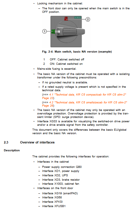
NA North American version special design: The main switch adopts Siemens components; The cabinet door can only be unlocked when the main switch is in the OFF position; Isolation transformer (ungrounded neutral grid) must be equipped; Mandatory installation of surge suppressors; Require external branch fuse protection.
Interface partitioning
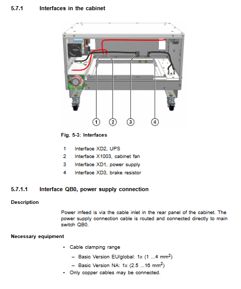
Cabinet interface: QB0 main power supply; XD1 power supply; XD2 UPS uninterruptible power supply; XD3 braking resistor; X1003 cabinet fan.
Front door interface (optional): XG19 (smartPAD), XG29 (smartPLUG), XG58 (external enable/emergency stop), XFKSI (KSI service network port) XFUSB1(USB)。
Cooling system: The bottom fan sucks in ambient air to dissipate heat from the controller power unit.
Available options: Wheel assembly, battery UPS module, front door interface kit, additional local emergency stop button, surge suppressor (transient limiter SPD).
Designated use and prohibition of misuse
Purpose: Used to accommodate and install KR C5 slim-2 robot controllers.
Misuse: Used for climbing stairs, operating beyond parameters, outdoors, explosion-proof areas, radioactive environments, underground mining. Misuse will result in loss of warranty.
Security
This chapter only applies to the cabinet body, and the complete safety rules for robots must refer to the KR C5 slim-2 controller assembly manual.
All operators must read the safety instructions, failure to comply may result in death, serious injury, and equipment damage.
After repairing the power outage, the maximum voltage of the intermediate circuit is 800V, and it is necessary to wait for at least 5 minutes for discharge; Strictly implement the 5-step electrical safety maintenance method (power-off, anti misoperation closing, electrical inspection, grounding short circuit, isolation of adjacent live parts); ESD anti-static is necessary for maintenance.
The emergency stop equipment has a maximum switching frequency of 250000 times over a 20-year lifespan, and must be replaced once the frequency is reached.
Technical data
General Electrical Conditions
Power supply: three-phase AC380/400/415/440/480V, ± 10%, 50-60Hz; must be grounded in a neutral star grid, and ungrounded neutral must be equipped with an isolation transformer.
Environmental temperature: Operating at -5~+45 ℃; Equipped with battery storage -20~+40 ℃; Dismantle the battery -20~+60 ℃; The maximum temperature change rate is 1K/min.
Altitude: ≤ 2000m without capacity reduction; For every 1000m increase between 2000-3000m, the power is reduced by 5% without automatic capacity reduction, requiring manual intervention.
Protection level IP54, the cabinet must be closed; Unused cable entrances must be sealed with plugs; Pollution level 2; Overvoltage category: ≤ 2000m Cat III; >2000m Cat II。
Vibration and shock: Running 0.5g continuously, shock 2g; transportation shock 10g half sine 11ms.
Noise level<71 dB (A); The allowable load for uniform distribution on the top of the cabinet is 1500N.
Leakage current ≤ 150mA; it is recommended to use a 300mA universal current type leakage protector for equipment protection only and not for personal protection.
Fuse: The global version has a minimum of 3 × 16A slow melting and a maximum of 3 × 20A; the NA North American version has a maximum of 15A Class CC/J fuse.
Differences between two cabinets
Parameters KR C5 compactcab KR C5 smallsizecab
The weight (empty cabinet without controller) is relatively light, about 35 kg
Dimensions 595 × 408.9 × 460mm 595 × 640 × 460mm
Stacking capacity: Up to 2 additional cabinets can be stacked
Install side by side with a gap of 50mm
Install minimum clearance
The minimum bending radius on the side of the cable is 150mm;
Heat dissipation: minimum 200mm above the front; 50mm between parallel cabinets; the rear must ensure free flow of hot air to prevent thermal accumulation from causing shutdown and shortening the service life.
Stacked installation: The lower cabinet must be fixed to the ground, and the upper cabinet must be fixed to the lower cabinet; The caster version prohibits stacking.
Nameplate label
The cabinet body is equipped with mechanical command signs, electric shock warnings, maintenance power-off prompts, and PE grounding signs; NA North American version adds arc flash warning; The nameplate cannot be removed and must be replaced if it is blurry.
REACH regulation: compliant with EU 1907/2006, detailed information can be found in KUKA Xpert.
System Planning
EMC electromagnetic compatibility: belongs to EN55011 Class A Group 1 industrial equipment; All external incoming lines use shielded cables, and the shielded large area is crimped and grounded.
Installation requirements
Capable of single machine landing, stacking, parallel arrangement, and optional casters; Casters are only used for short distance translation inside the cabinet group, and vehicle dragging is prohibited.
The environment prohibits conductive dust and condensation; Environmental cabinets with pollution levels 3-4 require additional protective enclosures.
Grounding requirements
The PE equipotential between the robotic arm and the controller is ≥ 16 mm ²; The control cabinet body is connected to the main PE row in the factory area, and it is recommended to use 16mm ² copper wire; Reserve PE bolts at the rear of the cabinet.
Cable laying
Fixed wiring bending radius ≥ 3-5 × cable outer diameter; The inner diameter of the drag chain is ≥ 7-10 times the outer diameter.
Separate the wiring of power motor cables and signal data cables;
After replacing the data cable of the robotic arm, all axes must be recalibrated; Fix the cables properly to eliminate the risk of tripping.
Interface Definition
Inside the cabinet: QB0 main power supply; XD1 power supply; XD2 UPS (24V, fault power outage maintained controlled shutdown; During the initial power outage, the maximum power is 6.5A, and during the shutdown phase, the maximum power is 4A. It is prohibited to operate without UPS as it may result in data loss; XD3 braking resistor.
Front door interface XG19/XG29/XG58/XFKSI/XFUSB1, pre installed wiring harness at the factory.
Transportation
Three transportation modes, prerequisites: power outage, removal of all cables, closure of cabinet doors, and upright cabinet body.
Lifting equipment: Use 4 M8 lifting bolts; Reasonable angle of the lifting rope, slow lifting, and prevention of swinging; The rated load of the empty cabinet is 40kg, with a controller of 75kg.
Forklift transportation: The fork teeth extend into the base of the cabinet, and the fork teeth open to contact the base to avoid squeezing the cabinet.
Wheel transportation: limited to short distance movement within the cabinet group; The ground must be flat; It is strictly prohibited to drag the wheels of the vehicle, as there is a risk of tipping over.
Power on and restart
Complete startup process
Position, confirm that the heat dissipation gap is met, visually inspect for transportation damage, and confirm that there is no condensation inside the cabinet.
Optional installation of caster components.
Connect PE equipotential protection grounding.
Slide the KR C5 slim-2 controller into the cabinet rail and lock it in place; The weight of the controller is about 25 kg to prevent crushing and injury.
Connect the motor cable and the data cable of the robotic arm, seal the cable entrance to ensure IP54 protection, and block any excess entrances with plugs.
Teaching pendant connection: two options, ① directly connected to the controller body; ② Connect cabinet door XG19.
Attention: Unplug the smartPAD, the teaching pendant’s built-in emergency stop will fail, and the system must retain the external emergency stop; Enable the switch to undergo functional testing at least once a year.
Battery: The factory battery protection plug must be disconnected and restored before operation before the UPS can work.
Connect the main power cable to the QB0 main switch terminal.
Check that all connectors are secure, and that the cables are not damaged or twisted.
Confirm that there are no people in the danger zone of the robotic arm and that the safety devices are complete; Close the main switch and the system will start.
Startup boot sequence: restore USB drive → external hard drive → internal SSD; Identifying external hard drives will disable internal hard drives.
Subsequent software debugging (refer to controller manual): machine data verification, no-load calibration, load calibration, TCP tool calibration, load data input, software limit, PLC external automatic interface configuration.
Run
The operation content refers to the KR C5 slim-2 controller manual, and this cabinet manual does not describe the human-machine operation of the controller.
Maintenance
maintenance cycle
Annual: Emergency stop equipment function testing.
Depending on the degree of pollution: Check and clean the internal and external protective grilles, as well as the controller’s heat dissipation fins.
Battery: Replace the entire battery when the battery monitoring alarm occurs.
Maintain mandatory security prerequisites
The main switch is powered off, locked, and tagged; Disconnect the incoming power supply; Wait for the intermediate circuit to discharge for at least 5 minutes; Comply with the 5 electrical safety regulations; ESD protection.
Prohibit compressed air and water spray cleaning; Use solvent-free neutral cleaning agents; Liquids are strictly prohibited from entering electrical components.
Maintenance inspection items: plug connection is tight, PE grounding is intact, cable insulation is not damaged, and all components are inspected for wear and damage.
Repair
Only repairs described in the document are allowed to be performed on-site; Personnel beyond the scope must be trained by KUKA; Only KUKA original spare parts can be used for spare parts, otherwise the warranty will be lost. Detailed steps for on-site replacement of components (unified process for each item: power-off safety operation → disassembly → replacement → assembly → power on test):
Cabinet base replacement (requires lifting the cabinet with a crane)
Replacement of cooling fan
CSP panel cable replacement
CSP (Controller System Panel) body replacement
Reactor replacement
Main filter box replacement
The replacement of the reactor and filter box requires the complete extraction of the KR C5 slim-2 controller module.
Troubleshooting
For details of alarms and faults, please refer to the KR C5 slim-2 controller assembly manual.
Discontinue, store, and dispose of scrap
Shutdown and retirement process: power off and lock; Confirm that there is no power supply in the incoming line; Disconnect the power cable; Pull out the controller module; Dismantle various types of cables.
Storage conditions: Indoor dry and dust-proof, avoiding condensation; Dismantle the battery and store it separately; Block the interface; Dust cover+desiccant; Follow the temperature range.
Scrap disposal: Metal copper, aluminum, steel, and electronic boards are used as electronic hazardous waste; Lead acid lithium batteries should be recycled according to regulations and should not be mixed with household waste.
Option installation
Wheel components: 2 brake equipped wheels, 2 free wheels; Need to lift the cabinet for installation; The brake must be locked in a stationary state; The caster version prohibits stacking.
Battery UPS components (12V 0.8Ah VRLA lead-acid, replacement in pairs)
Factory battery protection disconnected, on-site restoration of fuse.
Before transportation, the battery must be disconnected to prevent discharge damage; When there is a malfunction, the battery pack must be replaced in pairs; Pay attention to polarity to prevent short circuits.
Front door interface kit (XG19, XG29, XG58, XFKSI, XFUSB1): all provide disassembly and replacement steps; It is prohibited to plug or unplug the XG58 safety interface when it is live; The maximum cable length for KSI network port is 100m; USB interface only allows passive peripherals.
Additional local emergency stop button: installed through the front door opening of the cabinet; Dual channel wiring connected to XG58 interface; The system integrator is responsible for integrating security logic and conducting complete emergency stop function testing after replacement.
Transient Surge Suppressor SPD: Only for use in AC version cabinets, with overvoltage relief protection.