BENDER RCMA475LY AC/DC sensitive residual current monitor
Main features of the product
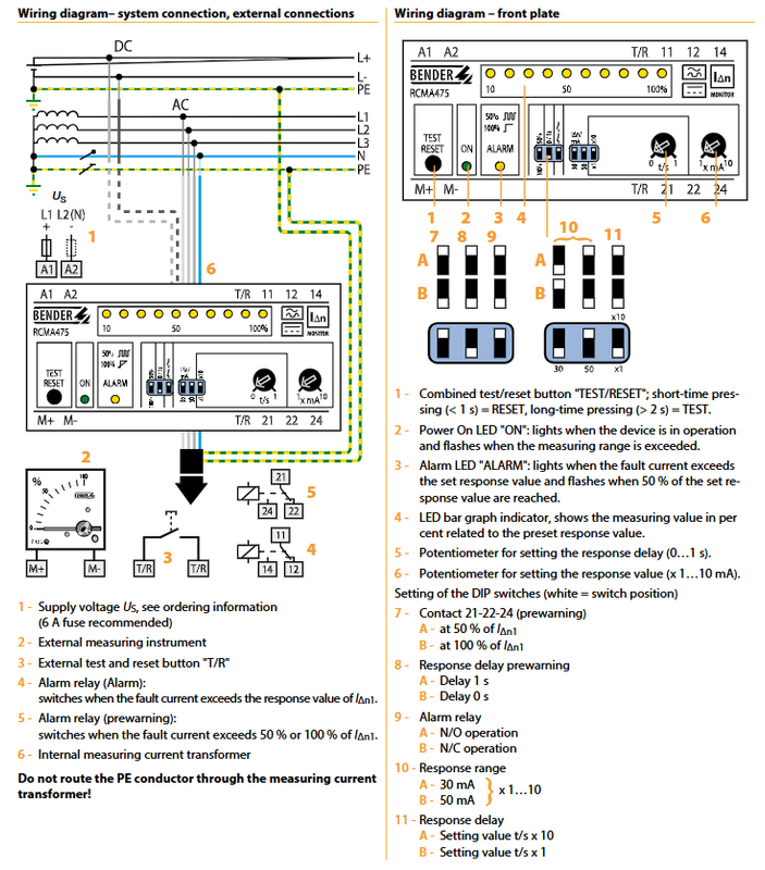
Built in measuring current transformer with an aperture of Φ 18mm; the main circuit cable passes directly through the transformer, and the PE protective ground wire is strictly prohibited from passing through the transformer.
Two level alarm threshold
Main alarm I Δ n1:30~500 mA, measuring frequency range 0-700 Hz;
Pre alarm I Δ n2: Fixed at 50% or 100% of the main alarm value, selected by dialing.
Adjustable response delay
Main alarm delay: potentiometer adjustment, 0-10 seconds;
Warning delay: choose one of two dialing options, 0 seconds/1 second.
Two independent alarm relays, each with one switching contact; The contact mode can be set to normally open NO/normally closed NC by dialing the code.
Fault memory latch: The alarm state will remain and needs to be reset and cleared;
Integrated TEST/RESET button: Short press<1 second to reset RESET; Long press>2 seconds to perform the function test TEST; Simultaneously supporting external T/R terminals connected to external test reset buttons.
status indicator
ON power light; ALARM alarm light;
LED bar chart: displays the current remaining current as a percentage relative to the set I Δ n1 (0-100%).
External measurement output: M+and M – terminals output 0-100% proportional signals, which can be connected to external pointer instruments.
Equipped with lead sealable transparent protective cover plate; External power supply; Type-B residual current detection.
Application scenarios
Suitable for TN and TT grounding systems, and can be used for 2/3/4 line AC/DC hybrid power supply systems:
Variable frequency drive and speed regulation drive equipment;
UPS uninterruptible power supply, six pulse rectification, unidirectional rectification with filtering, battery charger;
Monitoring of AC/DC mixed residual current for normal uncharged conductors (N neutral wire, PE protection wire).
Working principle: Built in core transformer collects residual current in the circuit; The residual current exceeds the set threshold, and the relay will activate after a set delay; Alarm status is locked and needs to be reset and cleared; The light column displays the percentage of leakage in real-time.
Panel coding and potentiometer configuration
potentiometer
T/s: main alarm response delay of 0-10 seconds;
I Δ n × 1/× 10: Set the main alarm current to 30-500 mA.
DIP dip switch
Warning trigger threshold: A=50% I Δ n1; B=100 % IΔn1;
Warning delay: A=1 s; B=0 s;
Relay contact mode: A=NO normally open; B=NC normally closed;
Measurement range gear: 30 mA/50 mA gear selection.
Meaning of LED indicator light
ON (green): The device is powered on and running; Flashing when exceeding the limit;
ALARM (yellow): Always on when reaching the main alarm threshold; Flashing when reaching the 50% warning threshold;
LED light column: 0-100%, visually observe the proportion of residual current to the alarm threshold.
Terminal Definition
A1/A2: Auxiliary power supply Us; it is recommended to equip the circuit with a 6A fuse;
M+/M —: External measuring instrument output;
T/R: External test reset button;
11-12-14: Main alarm relay conversion contact;
21-22-24: Pre alarm relay conversion contact.
Key technical parameters
Measurement performance
Type: IEC/TR60755 Type-B, capable of measuring AC, pulsating DC, and smooth DC leakage;
I Δ n1 alarm: 30-500 mA, 0-700 Hz;
I Δ n2 warning: 50%/100% of I Δ n1;
Response time: Under the condition of tv=0s, 1 times I Δ n1 ≤ 70 ms, 5 times I Δ n1 ≤ 40 ms;
The relative uncertainty of the measurement is about ± 25%, and the hysteresis is about 25% I Δ n.
Relay output contact
2-channel conversion contacts; Support NO/NC configurable; Equipped with fault memory latch;
Contact rating: AC/DC150V, 5A; AC230V cut-off 0.2A (cos φ=0.4); DC220V (L/R=0.04s) breaking 0.2A; electrical life 12000 times.
Environment and Machinery
Working temperature: -25 ℃~+70 ℃; Storage -40~+75 ℃; Climate level 3K5;
Anti impact and vibration comply with the IEC60068 series; EMC meets EN61543 and EN61000-6-4 standards;
DIN rail installation, UL94-V0 flame retardant shell; Weight ≤ 350 g;
Dimensions (mm): Width 99 x Height 73 x Thickness 65; Screw hole diameter is 4.3.
power supply
External auxiliary power supply Us, power consumption ≤ 3.5 VA; available in multiple power supply versions, order according to model.
Ordering model and supporting accessories
Order model number
RCMA475LY-B (B9404 2002): Industrial and Household;
RCMA475LY‑13(B9404 2004);
RCMA475LY-21-23 (B9404 2014/2015) is for industrial use only.
Optional external supporting components
96 × 96 external display instrument (Art-No 986807), reading 0-100% residual current;
RK170 signal conversion module: Input 0-400 μ A, output 0-10V/4-20mA standard analog signal, can be connected to PLC.
Important precautions
PE protection wires are strictly prohibited from passing through built-in transformers, otherwise the measurement will be completely ineffective; Only pass L1/L2/L3/N through the through-hole window;
Fault alarm status is locked and will not be cleared when powered off. The reset button must be pressed;
The TEST button only performs device self-test and is not equivalent to a functional test of leakage protection;
Pre alarm can provide early warning of the gradual increase of leakage, and the main alarm should be triggered for tripping or important alarms;
This device is a monitor and does not have a power trip output. It only outputs relay dry contacts and requires an external contactor/PLC to cut off the circuit.
Standard basis
IEC 62020, IEC/TR60755 Amendment 2, IEC60664-1 Insulation Coordination, DIN‑EN62020。