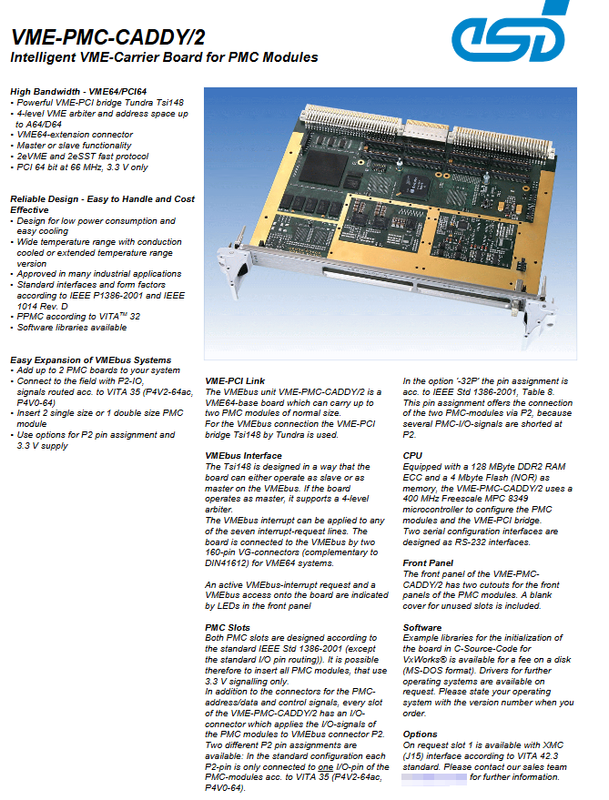
Esd VME-PMC CADDY/2 Intelligent VME-PMC Carrier Board
Core product positioning
VME-PCM-CADY/2 is a VME64 standard motherboard that enables protocol conversion between the VME bus and PCI (PMC) daughter cards. Can insert 2 single size PMC modules or 1 dual size PMC module; The PMC daughter card I/O signal is led out through the VME backplane P2 connector. Onboard Freescale microcontroller, used for configuration management of the board itself and PMC modules.
Main hardware features
1. VME-PCI bridge chip: Tundra Tsi148
VME side: Supports VME64, 2eVME, and 2eSST high-speed transmission protocols; Can be used as a VME master or slave device; Integrated Level 4 VME bus arbiter; Support A64/D64 large address space; Support 7 VME interrupt lines; Geographic addressing mode.
PCI side: 64 bit, 66MHz PCI bus, only supports 3.3V signal level.
Backplane connector: P1 and P2 are both 160 pin VG type VME64 expansion connectors, compatible with DIN41612.
Front panel LED indicator: Indicates VME bus interrupt requests and VME bus access activity status.
2. PMC slot (following IEEE 1386-2001)
Quantity: 2 single size PMC slots; Compatible with 1 dual size PMC; Only supports 3.3V signal PMC module.
I/O routing (P2 backplane) offers two hardware versions:
Standard version: Following VITA35 (P4V2-64Ac, P4V0-64), each pin of P2 is only connected to the I/O signal of one PMC, and the signals between the two PMCs are isolated from each other without interconnection.
32P2 version: Following the definition in Table 8 of IEEE1386-2001, some P2 pins are short circuited between two PMC slots to achieve interconnection between PMC modules through backplane P2.
Optional upgrade: Slot1 supports XMC (J15) interface (VITA42.3), which needs to be customized separately with sales.
The 3.3V power supply for PMC is provided by the VME backplane; Optional onboard 3.3V generation circuit.
3. On board management CPU subsystem
Main controller: Freescale MPC8349, with a main frequency of 400MHz.
Memory: 128MB ECC checksum DDR2 RAM; 4 MB NOR Flash.
Configure debugging interface: Two RS-232 serial ports, used for board cards PMC、 Configuration management of bridge chips.
4. Mechanical and environmental specifications
Exterior specifications: 6U, 4HP VME board; Size: 160mm × 233mm.
Working temperature version:
Version Temperature Range Order Number
Standard commercial version 0 ℃~+50 ℃ V.1915.02/V.1915.11
Wide temperature extension version -40 ℃~+75 ℃ V.1915.03/V.1915.13
Conductive cooling reinforced version -40 ℃~+75 ℃ V.1915.04
Humidity: Maximum 90%, no condensation.
Front panel: Reserve two PMC front panel openings with blank blocking plates for unused slots.
Overview of System Architecture Block Diagram
The VME backplane P1/P2 signal enters the Tundra Tsi148 bridge chip;
Bridge conversion generates 64 bit/66MHz PCI local bus, mounting PMC Slot1 and Slot2; Slot1 expandable XMC sub card;
MPC8349 manages MCU connections to Flash, DDR2 memory, and two RS-232 configuration serial ports, and is responsible for initializing and configuring bridge chips and PMC modules;
The PMC module I/O signal is routed and output to the VME backplane P2 connector.
Software support
Provide VxWorks operating system C source code library (paid, MS DOS format disk media, order number V.1915.58) for board initialization.
Other operating system drivers need to be separately applied to the manufacturer, and the operating system and version number need to be specified when placing an order.
There is no universal operating system built-in driver, relying on ESD to provide library files.
Complete order model description
Order number Product description
V. 1915.02 standard temperature; VITA35 P2 routing, isolation between PMCs; No XMC
V. 1915.03 wide temperature range -40~+75 ℃, the rest is the same as V.1915.02
V. 1915.11 standard temperature; 32P2 mode, P2 interconnection between PMCs; No XMC
V. 1915.13 Wide temperature range -40~+75 ℃, the rest is the same as V.1915.11
V. 1915.04 conduction cooling CC version, -40~+75 ℃; Standard VITA35 P2 router