Siemens SINUMERIK Measurement Cycle User Guide
1. Scope of application and basic information
Adaptation system: SINUMERIK 840/840C/850/880/880 GA2
Software requirements:
Minimum software version for control system
840/840C SW 01
850/880 SW 04
880 GA2 SW 01
Measurement cycle: V20 and above versions
2. Core measurement classification and functions
(1) Tool measurement (lathe)
Cycle: L972/L982
Function: Probe calibration, tool length/radius measurement, automatic compensation
Applicable tool types: 1-10, 26, 28, 31-38 types
Measurement modes: manual measurement, automatic measurement, mirror measurement
(2) Probe calibration
Lathe: L973, supports calibration of any surface/hole
Milling machine/machining center: L976, supports calibration of reference holes/arbitrary holes/reference surfaces
Calibration purpose: Determine the coordinates of the trigger point of the probe and store them in the MDC area
(3) Workpiece measurement
Lathe (L974): Single point/180 ° flip/two-point/multi-point circumference/cylindrical measurement
Milling machine/machining center:
L977: Axial measuring hole/shaft/groove/web plate, zero point setting
L978: Plane/angle measurement, differential measurement
L979: 2D measurement at any angle (3/4 point circle measurement)
Core ability: Automatically calculate actual dimensions, center coordinates, and deviation values
3. Definition of key parameters
R10: Compensation number (tool compensation/workpiece zero point G54-G58)
R22: Probe type (0=multi-directional, 1=unidirectional)+Probe number
R23: Measurement mode (calibration/measurement/automatic, axial/angular)
R25: Measurement speed (default 150mm/min)
R28: Measurement path magnification (default 1mm)
R33-R37: Tolerance parameter
Parameter meaning
R33 Zero offset interval (without compensation threshold)
R34 2/3 workpiece tolerance (average compensation threshold)
R36 Safety Zone (Out of tolerance shutdown)
R37 size difference inspection (tool wear warning)
R40/R41 workpiece upper and lower tolerances
4. Types of probes and usage rules
Multi directional probe (3D): fully functional and unrestricted, universal for lathes/milling machines
Bidirectional probe: only used for measuring lathe workpieces
Unidirectional probe: only used for measuring milling machine workpieces, requires M19 spindle positioning
Tool compensation type:
Lathe: Set the measuring head to 5/6/7/8 type cutting tools
Milling machine: probe set to 30 type tool
5. Measurement principle and accuracy
Measurement method: online measurement, NC directly processes probe signals, no PLC transfer
Repetition accuracy: ± 1 μ m
Average Algorithm: Weighted Average Formula Av_new=Av_old – (Av_old Di)/k, k=R29 Weighted Coefficient
Accuracy influencing factors: machine tool repeatability, probe repeatability, measurement system resolution
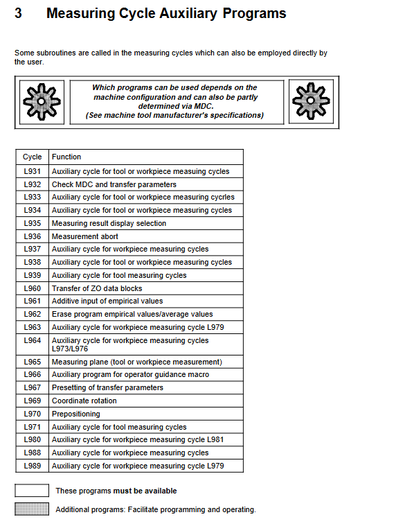
6. Auxiliary functions and alarms
Auxiliary cycle: L965 (measurement plane determination), L988 (measurement result log), L963 (center calculation)
Log output: Supports CP315 module, print output, results stored in R200-R219
Alarm mechanism: Safety zone out of tolerance, size out of tolerance, tool wear, probe failure alarm
7. Preconditions for use
Return to the reference point for completion
Turn off coordinate rotation and scaling
Call L965 to set the measurement plane before measurement
The probe has been calibrated and the parameters have been defined in advance
Key questions and answers
Question 1: What types of probes are set in the TOA memory for the lathe and milling machine respectively?
answer:
Lathe: Set the calibration tool to type 3 and the workpiece probe to type 5/6/7/8;
Milling machine/machining center: The workpiece probe is set to type 30.
Question 2: What are the functions of the four tolerance parameters R33, R34, R36, and R37 in the measurement cycle?
answer:
R33: Zero offset interval, no compensation is performed for deviations within this range;
R34:2/3 workpiece tolerance, if exceeded, perform average compensation;
R36: Safe zone, exceeding automatic shutdown and alarm;
R37: Dimensional difference inspection, if exceeded, it indicates tool wear and can continue to operate.
Question 3: What is the core difference between the L977 and L979 workpiece measurement cycles?
answer:
L977: Only supports * * axial (parallel coordinate axis) * * measurement, suitable for standard holes/axes/slots/belly plates;
L979: Supports 2D measurement at any angle, and can calculate the arc with the center outside the machine tool through 3/4 point measurement, requiring M19 spindle positioning.