Allen Bradley 1336 PLUS series AC frequency converter
Product positioning and basic information
Product Model: 1336 PLUS AC Variable Frequency Drive
Power range: 0.37-448 kW (0.5-600 HP)
Firmware version: FRN 1. xx~5. xx
Voltage level: 200-240V/380-480V/500-600V three-phase
Control mode: sine PWM, V/Hz, sensorless vector, process PI closed-loop
Frequency range: 0-400 Hz
Overload capacity: 150% for 1 minute (constant torque)
Safety and General Standards
Safety Warning
High voltage electric shock risk, wait for the DC bus to discharge to 0V after power outage
The device is ESD sensitive and requires anti-static measures during disassembly and assembly
Models with a power greater than 45kW cannot use firmware versions lower than 1.07
Model coding rules
1336S+voltage code+power code+protection code+language code
Protection: IP20, IP54 (NEMA12), IP65 (NEMA4)
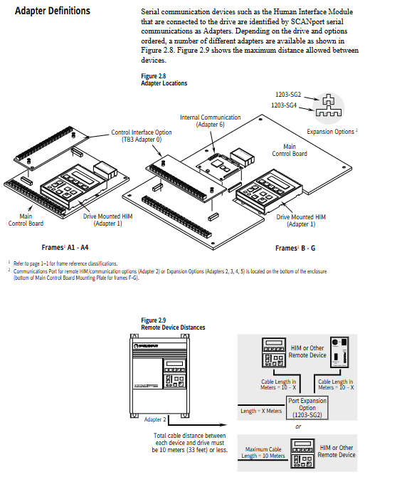
Nameplate location
A1-A4: Main control board installation board
B-G: Bottom of the chassis
Installation and wiring specifications
1. Installation requirements
Installation direction: Vertical installation
Heat dissipation spacing: left and right ≥ 30mm, up and down ≥ 100-152mm
Environmental temperature: 0-40 ℃ (closed)/0-50 ℃ (open)
Altitude: ≤ 1000m without capacity reduction
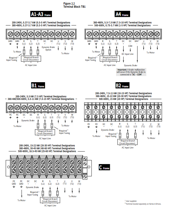
2. Main circuit wiring (TB1)
Terminal function
R/S/T (L1/L2/L3) three-phase power input
U/V/W (T1/T2/T3) motor output
PE safety grounding
DC+/DC – DC bus, braking resistor
3. Control circuit wiring (TB2/TB3)
TB2:0–10V、4–20mA、 Pulse input, relay output
TB3: Switching control, encoder feedback (L4/L5/L6/E versions)
Encoder: 5V/12V, differential/single ended, up to 125kHz
4. Protection and EMC
Input fuse: Match Class CC/J/T or gG according to the model
Grounding: Single point low impedance grounding, grounding at both ends of the motor cable shielding layer
EMC: RFI filter is required to meet CE requirements, and the power line and signal line must be separated
5. Maximum length of motor cable (380-480V)
table
Model without components, terminal, and reactor
A Frame 12.2m 91.4m 182.9m
B–C 12.2m 182.9m 182.9m
D–G 30.5m 182.9m 91.4m
Human Interface Module (HIM)
Core buttons
ESC/SEL: Exit/Select
Start stop, jog, direction, increase/decrease
Operation Mode
Display mode (read-only)
Programming mode (read-write)
Process mode (custom monitoring)
EEPROM mode (factory reset, parameter download)
Password mode (permission protection)
Search mode (check for non default parameters)
core functionality
Fault queue: View the last 4 faults
Logic shielding: Hot plug HIM does not report errors
Customize the power on display interface
Start debugging process
Power off → Disconnect motor → Power on → Restore factory parameters
Set Input Mode → Power off and restart to take effect
Write on motor nameplate: voltage/frequency/current/speed
Select control mode: Vector/V/Hz
Set maximum/minimum frequency and acceleration/deceleration time
No load test run → Calibration direction → Setting magnetic flux/slip
Connect the motor to load → optimize the slip gain and magnetic flux rise time
Set electronic overload, DC braking, and jump frequency
Parameter programming system
The parameters are divided into 14 functional groups, with the core as follows:
Set up a group
Input mode, maximum frequency 60Hz, acceleration/deceleration 10s, current limit 150%
Motor control group (FRN 4.01+)
Sensorless vector V/Hz、 Power Saving Mode
Initial boost, operational boost, inflection point voltage/frequency
Frequency setting group
Preset speed of 7 segments, jump frequency of 3 points, jog frequency of 10Hz
I/O configuration group
Analog calibration, relay output, analog output
Fault group
Fault cache, clearing method, grounding warning, disconnection protection
Fault diagnosis and protection
1. Common faults (example)
Fault code name and reason
F05 overvoltage deceleration fast, regenerative energy, high power grid
F07 motor overload load, improper protection current setting
F08 overheating and poor heat dissipation, fan failure
F12 overcurrent output short circuit, fast acceleration, motor failure
F13 grounding fault motor/cable grounding
F10 communication failure SCAnport device disconnected
2. Protection function
Overcurrent, overvoltage, undervoltage, overload, overheating, grounding, phase to phase short circuit
Power drop crossing 15ms, logic crossing 0.5-2s
Electronic thermal relay Class10, capable of reducing capacity according to speed ratio
Technical specifications and certification
environment
Humidity: 5-95% RH (no condensation)
Vibration: 1G, Impact: 15G
electrical
Power factor: 0.95 (A4 or above)
Efficiency: 97.5%
Carrier frequency: 2-10kHz (different models)
certification
cULus、CE、CSA
Compliant with EN61800-6-4/6-2 and EN55011
Key issues
Question 1: What are the core control modes of the 1336 PLUS frequency converter? What scenarios are they applicable to?
answer:
V/Hz control: General scenario, multiple motors in parallel, fans and pumps, simple speed regulation, and simple parameter configuration.
Sensorless vector control: high-precision speed regulation, fast torque response, suitable for conveyor belts, presses, and single motor speed regulation.
Process PI closed-loop control: a process system that requires pressure/flow/liquid level closed-loop.
Energy saving mode: Long term operation under light load, automatically reducing output voltage to save energy.
Question 2: What motor parameters must be set during startup debugging? What are the consequences of setting errors?
Answer: It is necessary to set the rated voltage, rated frequency, rated current, and rated speed of the motor. Consequences of Error:
Voltage/frequency error → abnormal V/Hz curve, insufficient torque or overheating.
Current error → Overload protection misoperation or failure to protect.
Speed error → vector control misalignment, low-speed instability, and runaway.
Question 3: What are the most common causes and quick solutions for overvoltage faults (F05)?
Answer: The most common reason is that the deceleration time is too short, and the regenerative energy of the motor causes the bus voltage to exceed the standard. Quick resolution:
Extend the deceleration time by half.
Enable Bus Limit En.
Install high power/high inertia braking resistors/braking units.
Check if the power grid is consistently high.