OMRON 3G3SV series book style fully digital low-noise frequency converter
Product basic information
Product Name: OMRON SYSDRIVE 3G3SV Book style All Digital Low Noise Inverter
Voltage level: 200V level (single-phase/three-phase)
Power coverage: 0.2kW/0.4kW/0.75kW/1.5kW/2.2kW/3.7kW
Model rules: 3G3SV Bxx (three-phase), 3G3SV BBxx (single-phase)
Display: 3-digit 7-segment LED, capable of displaying frequency/current/fault codes
Operation mode: External terminal (default), optional digital operator
Installation specifications
Environmental Requirements
Environmental temperature: -10 ℃~+50 ℃
Protection: moisture-proof, dust-proof, corrosion-resistant, no direct sunlight
Installation direction: Vertical installation to ensure heat dissipation
Spacing: at least 120mm up and down, and at least 10mm left and right
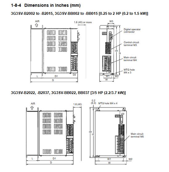
Installation dimensions (brief table)
Power segment width, height, and depth
0.2~1.5kW 70~72mm 250mm 174~230mm
2.2~3.7kW 150mm 250mm 230mm
Wiring instructions
1. Main circuit terminal
Terminal function
L1 (R)/L2 (S)/L3 (T) power input (single-phase only connected to L1/L2)
T1 (U)/T2 (V)/T3 (W) output connected to motor
B1/B2 brake resistor connection
G (E) grounding terminal
2. Control circuit terminal (core)
Terminal number function
1. Running/stopping in forward direction
2 Reverse operation/stop
3 External fault inputs
4. Fault reset
5/6 multi-stage speed setting 1/2
11 4~20mA frequency given
13 0~10V frequency given
18 analog frequency meter output (0~10V)
19 Analog output common terminal
3. Wiring safety requirements
After power failure, wait for the CHARGE light to turn off before operating
It is strictly prohibited to connect the power supply to the output terminals T1/T2/T3
Grounding resistance * * ≤ 100 Ω * *, independent grounding is optimal
Separate wiring for power and control lines
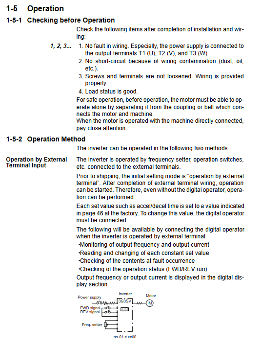
Run operation
Two control modes
External terminal control (default)
Controlled by external switches and potentiometers for start stop and frequency
Parameter: no-01=xx00
Digital operator control
Operated by panel RUN/STOP/FWD/REV
Parameter: no-01=0011
Trial operation steps
Check the wiring for accuracy and disconnect the load
Power on, set the rated current of the motor
Start and check for steering, sound, and vibration
Adjust acceleration and deceleration time (default 10 seconds)
Core parameter settings
Common parameter summary table
Default value range for parameter number function
01 Operation mode selection 0000-
02 Maximum frequency 60.0Hz 50~400Hz
04 Base frequency 60.0Hz 0.1~400Hz
09 Acceleration Time 1 10.0s~600s
10 deceleration time 1 10.0s 0~600s
17 point moving frequency 6.0Hz 0~400Hz
The rated current of the 19 motor ranges from 10% to 120% according to the model
22 frequency given gain 1.00-
27. DC braking time during stop: 0.5s~5s
Advanced features
9-stage multi-stage speed: terminal 5/6/7 combination setting
S-curve acceleration and deceleration: suppressing mechanical impact
Frequency jump: Avoid resonance points
Speed search: Power outage recovery and restart
Protection and fault diagnosis
protection function
OC: Overcurrent (>200% rated)
OV: Overvoltage (DC>410V)
UV: Under voltage (DC < 210V)
OH: Overheating of radiator (>90 ℃)
GF: Grounding fault
OL1/OL2: Motor/frequency converter overload
OL3: Over torque detection
CPF: Control circuit failure
Principles of fault handling
Record fault codes
Check the load, wiring, and parameters
External reset or power-off restart
Repeated faults need to be returned to the factory for repair
Maintenance and Inspection
Regular inspection items
Tightening torque of terminal screws 4~6kg · cm ²
The lifespan of the cooling fan is approximately 20000 hours
Whether the filtering capacitor has bulges or leaks
Clean environment, no dust or oil stains
Maintenance requirements
Power off and confirm that the CHARGE light is off before operation
Cannot be subjected to withstand voltage testing
Fan malfunction, replace immediately
Key issues
Question 1: What are the two control modes of G3SV frequency converter? How to switch?
answer:
External terminal control (factory default): controlled by external buttons and potentiometers;
Digital operator control: directly controlled by panel buttons.
Switching method: Enter parameter no-01 and set it to 0011 to switch to panel control.
Question 2: What is the most dangerous mistake in the wiring of the 3G3SV main circuit? What consequences will it cause?
Answer: The most dangerous mistake is to connect the AC power supply to the output terminals T1/T2/T3 of the frequency converter. Consequence: It will directly burn out the internal power module of the inverter, which cannot be repaired and can only be replaced as a whole machine.
Question 3: What are the common causes and solutions for OC overcurrent faults in frequency converters?
Answer: Common reasons:
Output short circuit and grounding;
The acceleration and deceleration time is too short;
Overloading and motor stalling;
The frequency converter does not match the motor capacity.
Processing method:
Check the insulation between the motor and the cable;
Extend acceleration and deceleration time (parameter 09/10);
Reduce load or increase the capacity of the frequency converter;
Reset and restart after eliminating the short circuit.