OMRON SYSMAC C20K/C28K/C40K/C60K series K-type programmable controllers
Basic Information
Applicable models: C20K, C28K, C40K, C60K
Core application: Small PLC ladder diagram programming, hardware operation, fault handling
Targeting personnel: Electrical engineers, equipment debugging, system designers
Safety and Installation Standards
Mandatory safety requirements
Power off operation is required, and it is forbidden to disassemble or connect the machine with power on
Grounding resistance * * ≤ 100 Ω * * to prevent electric shock and interference
Prohibited for use in high-risk scenarios such as medical, aviation, nuclear safety, etc
Environmental Requirements
Working temperature: 0-55 ℃, no condensation, no corrosive gas
Stay away from strong electromagnetic, static electricity, and direct sunlight
Hardware and indicator lights
Panel indicator lights: POWER, RUN, ERR, ALARM
Expansion rule: Up to 5 units can be mounted, with C40K/C60K counted as 2 units
Total length of cable: ≤ 1.2 meters
Memory area allocation (core)
Regional abbreviation address range function, power failure maintenance
Internal relay IR 0000-1807 I/O mapping, intermediate variable no
Special relay SR 1808-1907 system flag, clock pulse no
Maintaining the critical state storage of relays HR HR000-HR915 is
Data storage DM DM00-DM63 numerical data storage is
Timer/Counter TC TC00-TC47 Timer/Counter Resource Section
Temporary relay TR TR00-TR07 ladder diagram branch temporary storage No
Key SR Logo
1808: Battery low voltage alarm
1809: Scan cycle timeout (>100ms)
1813: Constant ON; 1812/1814: Constant OFF
1900/1901/1902:0.1S/0.2S/1s clock pulse
1903-1907: ER/CY/GR/EQ/LE operation flags
Programming Mode and Operation
Three working modes
Program: programming, clearing memory, syntax checking
MONITOR: monitoring, forcing, modifying parameters
RUN: Normal operation, program modification is prohibited
Programmer operation
Password unlocking, memory clearing, instruction input/insertion/deletion
Program search, syntax check, scan time display
Programming rules
The program must end with * * END (01) * *
The output bit can only be driven by one OUT command, and duplicate coils are prohibited
Implement branches using TR00-TR07 or IL/ILC
Core Instruction System
1. Logical instructions (basic)
LD/LD NOT: Load normally open/normally closed
AND/AND NOT: series connection
OR/OR NOT: Parallel connection
AND LD/OR LD: Block Logic
2. Process instructions
OUT/OUT NOT: Output
DIFU/DIFD: rising edge/falling edge (limited to 48)
KEEP: Latch Relay
IL/ILC: Interlock/Reset
JMP/JME: Jump (numbers 00-08)
3. Timing and Counting
TIM: 0.1s timer (0-99.9s)
TIMH: 0.01s high-speed timer
CNT: Down Counter
CNTR: Reversible Ring Counter
HDM (61): 2kHz high-speed counter (occupying TC47)
RDM (60): Reversible circular counter (occupying TC46)
4. Data processing instructions
MOV/MVN: Transfer/Reverse Transfer
CMP: Comparison (affecting GR/EQ/LE)
ADD/SUB/MUL/DIV: BCD operation
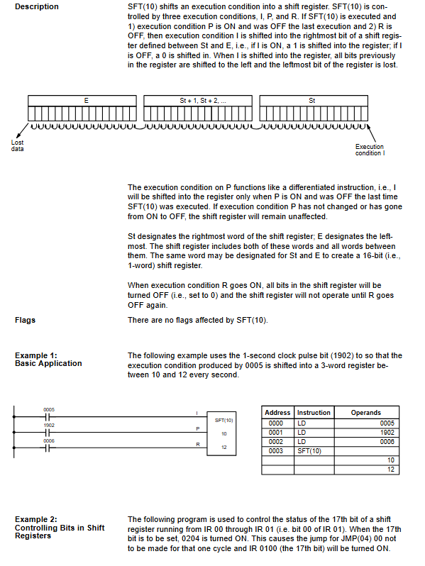
SFT/SFTR: Shift Register
Debugging and troubleshooting
debugging tool
Program syntax check, scan cycle monitoring
Force bit, modify current/set value
Common mistakes
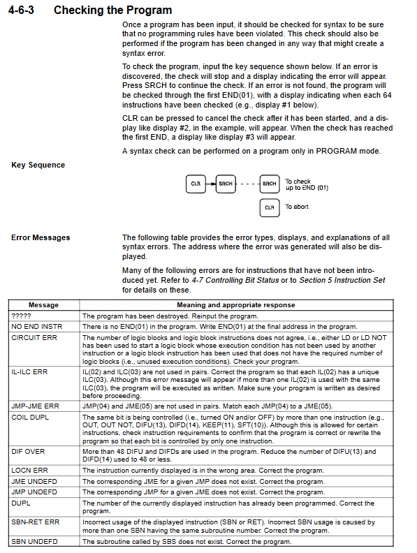
NO END INSTR: Missing END instruction
CIRCUIT ERR: Logical block mismatch
IL-ILC ERR: Interlock mismatch
COIL DUPL: Repetitive output coil
JMP-JME ERR: Jump not paired
Key issues
Question 1: Which of the 6 memory regions of the C-series PLC support power down hold? What are their respective purposes?
Answer: HR (holding relay) and DM (data storage) support power-off holding.
HR is used to save key information such as start stop status, alarm records, and mode selection;
DM is used to store textual data such as parameters, cumulative values, formula data, etc., without loss during power outages.
Question 2: What is the difference between TIM and TIMH instructions? How to choose in the program?
answer:
TIM: Time base of 0.1 seconds, range of 0-99.9s, low accuracy, suitable for conventional delays;
TIMH: Time base of 0.01 seconds, range of 0-99.99 seconds, high accuracy, suitable for fast timing.
Selection rule: TIM must be used for at least 1 second; Requires<1 second high precision * * using TIMH.
Question 3: IL/ILC and JMP/JME are both process controls. What are the core differences and applicable scenarios?
answer:
IL/ILC (Interlock): Reset timer and clear output when conditions are not met, suitable for safe shutdown and emergency stop logic;
JMP/JME (Jump): Keep all outputs/states unchanged when conditions are not met, suitable for energy-saving skipping and function blocking.
Simple note: To cut off the output, use IL; to maintain the output, use JMP.