Yaskawa ∑ – V series SGDV servo drive matching
Product scope and specifications
Applicable Products
Driver: SGDV series (FE100V/AE200V/DE400V)
Motors: SGMJV, SGMAV, SGMPS, SGMGV, SGMSV, SGMCS
Power: 0.05kW – 15kW, covering low to medium to high power
Voltage and current specifications (core table)
Series Voltage Continuous Current Maximum Current Regenerative Resistance
SGDV-FE single-phase 100V 0.66-2.8A 2.1-9.3A external
SGDV-AE three-phase 200V 0.66-78A 2.1-170A internal/external
SGDV-DE three-phase 400V 1.9-37.2A 5.5-85A external
Basic Performance
Control mode: IGBT-PWM sine wave drive
Encoder: 13/17/20 bit incremental/absolute value
Speed range: 1:5000
Speed fluctuation rate: ± 0.01% (rated speed)
Working temperature: 0-55 ℃
System architecture and interfaces
Main interfaces
CN1: I/O signals (Servo ON, P-OT/N-OT,/COIN, etc.)
CN2: Encoder connection cable
CN3: Digital Operator JUSP-OP05A-1-E
CN5: Simulation monitoring (speed/torque)
CN7: USB communication (SigmaWin+)
CN8: Safety features (HWBB1/2, EDM)
Security Core
HWBB (Hardwired Base Block): Dual input, forced output cut-off
EDM: Safety Circuit Monitoring Output
Standards: EN954-1, IEC61508 SIL2
Operation mode (three core)
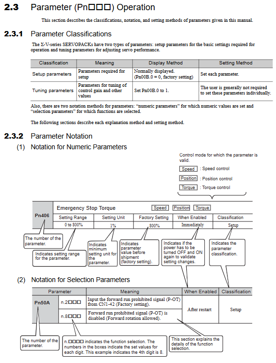
1. Parameter mode (Pn)
Basic settings: Control mode, electronic gear, acceleration and deceleration
Gain adjustment: position loop, speed loop, torque limiting
Protection settings: overcurrent, overvoltage, overload threshold
2. Function mode (Fn)
Fn002: JOG jog operation
Fn003: Origin Search Z-Search
Fn005: Parameter initialization
Automatic tuning, filtering settings, alarm clearing
3. Monitoring mode (Un)
Un000: Real time motor speed
Un001: Torque command
Un002: Position deviation
Un008: I/O Status
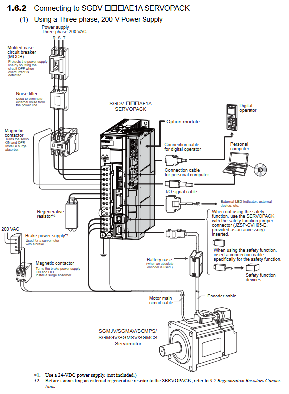
Wiring specifications (mandatory safety)
Main circuit: L1/L2/L3 input, U/V/W connected to motor
The terminal can only be accessed after the CHARGE light is turned off (power outage delay)
Grounding: Grounding resistance ≤ 100 Ω
Brake motor: independent 24VDC/90VDC power supply
Safety function: CN8 must be short circuited when not in use
Alarm and protection
Display format: A.xxx alarm code
Common faults:
A. 00 overcurrent
A. 10 Overvoltage
A. 30 overload
A. E6 encoder abnormality
Processing: Record code → Check wiring/load/parameters → Reset
Maintenance cycle
Component replacement cycle
Cooling fan 4-5 years
Main capacitor 7-8 years
Electrolytic capacitor for 5 years
Annual inspection of appearance, screws, heat dissipation, and dust
Key issues
Question 1: What are the three main operating modes (Pn/Fn/Un) of the ∑ – V servo responsible for, and which functions are most commonly used on site?
answer:
Pn (parameters): Core settings such as control mode, electronic gear, gain, protection, etc.
Fn (Function): During on-site debugging, JOG jog, origin search, parameter initialization, and automatic tuning are the most commonly used.
Un (monitoring): Real time monitoring of speed, torque, position deviation, and I/O status for troubleshooting.
Question 2: What is the function of the CN8 interface for the safety feature of SGDV drivers? What must be done when not using security features?
answer:
CN8 is used for HWBB hard wired base block, achieving the highest level of safety cut-off such as emergency stop and safety door.
When the safety function is not in use, the factory provided short-circuit plug must be installed, otherwise the drive cannot turn on Servo ON.
Question 3: Why can’t the ∑ – V servo be operated immediately after power failure? What is the function of CHARGE light?
answer:
The large capacity capacitors inside the driver may retain high voltage, posing a risk of electric shock when in direct contact.
If the CHARGE light is on, it indicates that there is still electricity inside. It is necessary to wait for the light to completely turn off (usually for more than 5 minutes) before wiring or disassembly can be carried out.