Siemens SIMATIC S5-90U/S5-95U Compact PLC
The official system manual for Siemens SIMATIC S5-90U/S5-95U compact PLC covers the entire process of hardware structure, installation and wiring, power on startup, STEP 5 programming, I/O addressing, interrupt/counter/analog processing, real-time clock (only 95U), SINEC L1 communication, module expansion, and fault diagnosis for small automation scenarios. The S5-90U is a basic economy model, and the S5-95U is a high-performance enhanced model that supports S5-100U series module expansion. It adopts STEP 5 instruction table/ladder diagram programming and has three execution modes of cycle/interrupt/time control. It provides three-level troubleshooting methods including LED status, diagnostic byte, ISTACK/BSTACK. It is part of this series. The authoritative basis for PLC installation, debugging, programming, and maintenance.
Product model and core specifications
The positioning of the two models is different, and the S5-95U has more comprehensive functions.
Parameter S5-90U S5-95U
Onboard I/O 10 in/6 out 16 in/16 out
Analog I/O without 8 inputs/1 output
Interrupt input 1 channel and 4 channels
Counter 1 channel (1kHz) 2 channels (2kHz/5kHz)
User memory 4KB 16KB
Real time clock not available
Communication SINEC L1 (Slave) SINEC L1/L2 (Master/Slave)
Power supply 115/230V AC 24V DC
Hardware structure and electrical configuration
core unit
CPU、RAM、ROM、 Process Image Area (PII/PIQ), Battery Backup Unit
Programming interface: 15 pin D-sub, supports programmer/upper computer/SINEC L1
Electrical isolation
Onboard I/O adopts optocoupler isolation
Analog quantities, counters, interrupts, and control circuits are grounded together and only support non floating grounding
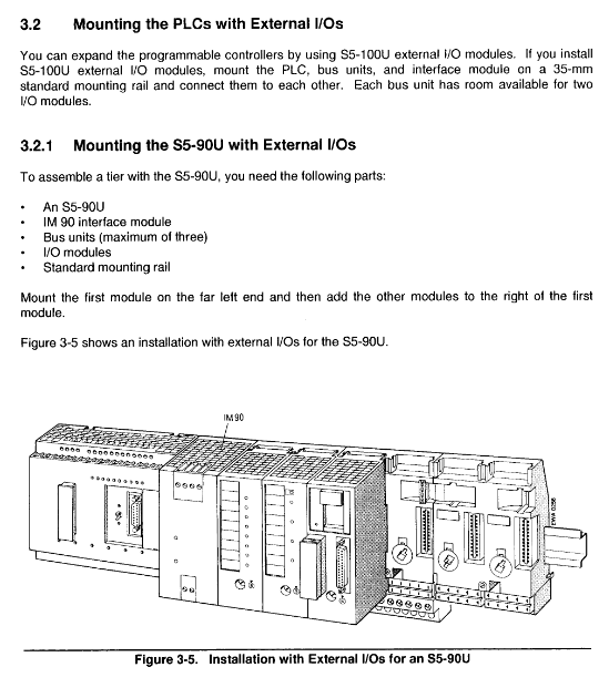
Installation and wiring specifications
Installation requirements
Method: 35mm rail or wall mounted (only 90U)
Spacing: Up and down ≥ 10cm, left and right ≥ 5cm
Environment: -10~55 ℃, no condensation, no dust
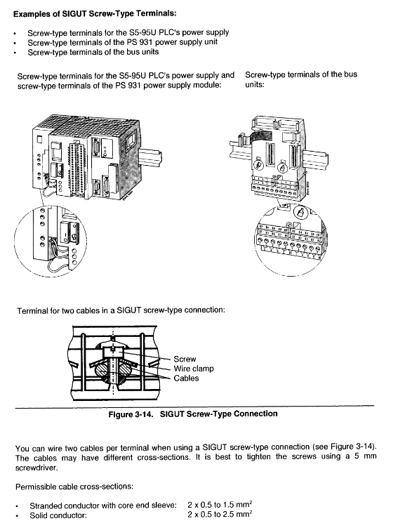
Key points of wiring
Digital I/O: 24V DC, grouped power supply, common M terminal
Analog quantity (95U): shielded wire, single ended grounded, length ≤ 50m
Interrupt/Counter: High speed signal, must be shielded, length ≤ 50m
Grounding: 400V system<10 Ω, 200V system<100 Ω
Operation mode and startup process
Three operating modes
STOP: Program stops, output is reset to zero
RUN: Loop program execution
Restart: Load DB1 parameters and execute OB21/OB22
Total cleaning operation (factory reset)
S5-90U: STOP → Remove battery → Power off for 15 seconds → Power on → Install battery
S5-95U: STOP → Remove battery → OFF → ON → Install battery
program loading
Auto: Power on and read from EEPROM
Manual (95U): Press and hold the COPY button to power on
STEP 5 Programming System
programming method
Instruction table STL, ladder diagram LAD, function block diagram CSF
Program block type
OB organizational blocks: OB1 (main loop), OB3 (interrupt), OB13 (timed)
PB program block: user-defined
FB Function Block: FB250 (Read Analog), FB251 (Write Analog)
DB data block: DB1 (system parameter)
SB sequential block (only 95U)
core instruction
Logic: A, AN, O, ON, X, XN
Timer: S5 timer, 10ms~9990s
Count: add count, 0~999
Transmission, comparison, arithmetic operation
Special functions (mainly exclusive to 95U)
Interrupt handling
4-channel interrupt input, fixed priority
Jump to OB3 after triggering, fast response
High-speed counter
2 independent counters, up to 5kHz
Support cascading into 32-bit counters
Analog signal processing
8 inputs, 1 output
Call FB250/FB251 read/write and calibration
real-time clock
Equipped with battery backup, supporting time comparison and running hour counting
communication
SINEC L1 bus, up to 31 stations
95U supports L2/DP and can be used as the main station
Diagnosis and troubleshooting
LED status
Green RUN: Running
Red STOP: Stop/Fault
Yellow BF (95U): Low battery
diagnostic tool
IB35 diagnostic byte: interrupt, count overflow, power, battery status
ISTACK: Interrupt stack, investigate the cause of the fault
BSTACK: Block Stack, Tracking Program Calls
Typical faults
Unable to enter RUN: Program error, DB1 error, I/O failure
Red light flashing: Program loading/saving failed
Key questions and answers
Question 1: What are the core hardware and functional differences between S5-90U and S5-95U?
answer:
I/O and Resources: 95U with 8 analog channels, 3 interrupts, 1 high-speed counter, and memory ranging from 4KB to 16KB.
Advanced features: 95U exclusive real-time clock, time control execution PID、 Dual serial port, SINEC L2 master station.
Expansion: The 95U can directly mount 16 bus units; 90U requires IM90, up to 3.
Question 2: How to quickly troubleshoot the fault of PLC being unable to switch to RUN mode (red light constantly on)?
answer:
Use a programmer to check ISTACK and locate the cause of the malfunction.
Check if the DB1 parameters are configured incorrectly.
Check the wiring and bus connection of the external I/O module.
Reinstall the program after executing the overall cleaning.
Check if the 24V/power supply is functioning properly and if the battery is installed.
Question 3: How to use the analog function of S5-95U? What functional blocks must be called?
answer:
Hardware: 8 analog inputs (IW40~IW54), 1 analog output (QW40), using shielded twisted pair cables.
Software: Read using FB250, output using FB251, complete engineering quantity calibration.
Restrictions: The analog port is not isolated and must be grounded together, with a cable length of ≤ 50m.