KEB COMBIVERT F5 elevator dedicated frequency converter
The official reference manual for KEB COMBIVERT F5 elevator specific frequency converter is aimed at 230V/480V, 0.2~250hp models, focusing on elevator safety control. It clarifies the strong safety regulations that require a 5-minute power outage and voltage drop to a safe value before operation. The system explains installation wiring, STO safe torque shutdown, multi type encoder adaptation, LCD panel operation, startup debugging, motor/encoder/inertia self-learning, speed curve, pre torque anti slip, and fault diagnosis throughout the entire process. It supports induction motor/permanent magnet synchronous motor, V/F/vector/FOC closed-loop control, built-in overcurrent, overvoltage, overload, brake transistor monitoring and other elevator specific protections, meeting EN81, UL508C, IEC61800 elevator safety standards. It is an elevator debugging tool. The core basis for maintenance.
Safety regulations (mandatory)
Operational Security
After power failure, wait for ≥ 5 minutes to confirm that the DC bus is not powered before operation
Only professional electrical personnel are responsible for installation, debugging, and maintenance
It is strictly prohibited to connect capacitors/surge absorbers on the output side
safety function
STO safety torque shutdown: compliant with IEC61800-5-2, SIL3/PLE
Brake transistor monitoring: K1/K2 normally closed contacts, power cut off due to fault
Motor overheat protection: supports PTC/KTY84 temperature sensor
Technical specifications
Key parameters of the project
Voltage level 230V (180~260V), 480V (305~528V)
Power range 230V: 7.5~100hp; 480V:7.5~250hp
Output frequency 0~599Hz, carrier frequency 1~16kHz
Overload capacity 150%/1min, low-speed current limiting protection
Safety certification EN81, UL508C, IEC61800, EN61000
Environmental temperature operation * * -10~45 ℃, storage -25~70 ℃**
Installation and wiring
Mechanical Installation
Vertical installation, with a distance of ≥ 10cm between the top and bottom, and ≥ 5cm between the left and right sides**
If the altitude is greater than 1000m, the capacity needs to be reduced by 1% every 100m**
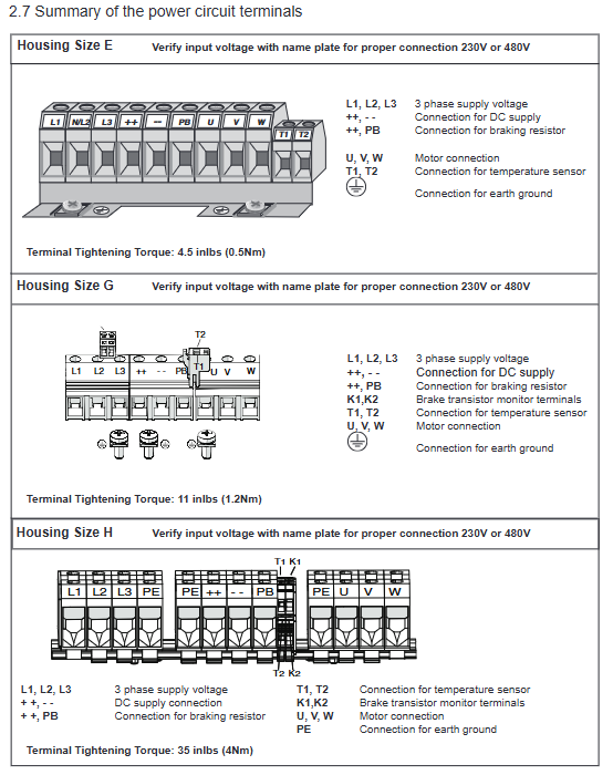
Main circuit wiring
Power supply: L1/L2/L3; Motor: U/V/W (reverse connection strictly prohibited)
Braking: PA/PB connected to braking resistor, following the minimum resistance value
Grounding: 480V < 10 Ω, 230V < 100 Ω, high-frequency shielding grounding
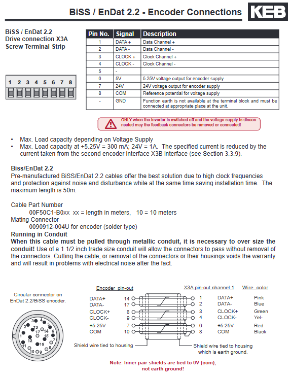
Encoder wiring
Support: TTL, EnDat, Sin/Cos, SSI, Hiperface, UVW
Cable: Shielded twisted pair, kept away from power lines * * ≥ 20cm**
Power supply: 5V/15V/24V optional, maximum load 300mA
Operation panel and permissions
LCD operation
Shortcut keys: F1 (recent), F2 (diagnostic), F3 (parameters), F4 (language)
Display: speed, current, bus voltage, fault information
Password permission
Basic (11): Read only
User (27): Basic Parameters
Adjuster (119): Advanced Debugging
OEM (479): All parameters
KEB: Manufacturer Permissions
Startup debugging process (core)
Basic Settings (US Group)
US02: Units (Imperial/Metric)
US03: Motor type (induction/PM)
US04: Control type (digital/binary/analog/serial)
US06: Rated speed
Motor parameters (LM group)
Input according to the motor nameplate: power, speed, current, voltage, frequency
PM motor requires additional input torque and automatically calculates the number of poles
Encoder parameters (LE group)
LE02: Pulse Count (PPR)
LE03: AB phase commutation
LE06: Magnetic pole position (PM motor)
Mechanical parameters (LN group)
The diameter of the pulley, reduction ratio, and winding ratio determine the conversion of elevator speed
Self learning (LL group)
LL01: Self learning of motor parameters
LL05: SPI Static Magnetic Pole Learning (PM Motor, No Displacement)
LL06: Encoder pole learning (requires slight displacement)
LL10: System Inertia Learning (Optimizing Comfort)
Core control function
Control mode (LC01)
0: V/F open-loop
1: Vector open-loop
2: FOC closed-loop+internal pre torque
3: Analog pre torque (connected to weighing)
4: Digital pre torque
5: Predictive synthesis pre torque (optimal for anti slip vehicle)
Speed curve (LS group)
Leveling speed, maintenance speed, high speed, acceleration and deceleration, Jerk curve
Support preset curves in three levels: soft, medium, and hard
Pre torque (anti slip vehicle)
Establish torque before opening the brake to eliminate starting the rolling car
No need for weighing sensors, adaptive load
Protection and malfunction
Complete protection
Overcurrent (E.OC), Overvoltage (E.OV), Overload (E.OL)
Overheating, undervoltage, phase loss, grounding fault
Encoder malfunction, brake transistor malfunction, brake feedback malfunction
Fault handling
Fault records with timestamp, supporting data recording
Reset: Panel F4 reset, some faults need to be confirmed by LE01
Key questions and answers
Question 1: What are the two learning requirements for PM permanent magnet synchronous motors? What are the consequences of failure?
The answer must be completed:
Motor parameter self-learning (LL01): Obtaining motor resistance and inductance
Magnetic pole position learning (LL05 SPI or LL06): determining encoder and rotor phase
Consequences of Failure:
Motor shaking, abnormal noise, and runaway
Excessive output current triggers overcurrent protection
The elevator slides and experiences significant vibrations during operation, making it unable to function properly
Question 2: How does the F5 frequency converter achieve elevator startup without slipping? What are the core settings?
Answer core solution: Closed loop FOC+predictive pre torque (LC01=5) Key settings:
LC01=5 (synthetic pre torque)
Complete Inertia Learning (LL10)
Adjust the brake timing (LT01~LT03)
Optimize pre torque gain (LC05/LC10)
Principle: The driver automatically calculates the load torque and outputs the corresponding torque before opening the brake, completely eliminating rolling.
Question 3: What are the three most common causes and troubleshooting steps for E.OC overcurrent faults?
Common reasons for answers:
Motor wire reverse/short circuit/grounding
Motor parameter error or incomplete self-learning
Acceleration too fast, encoder abnormal, brake not open
Troubleshooting steps:
Check the U/V/W wiring and confirm that there is no short circuit or grounding
Check the motor nameplate parameters and re execute LL01 motor learning
Extend acceleration time (LS20), check encoder signal and brake feedback