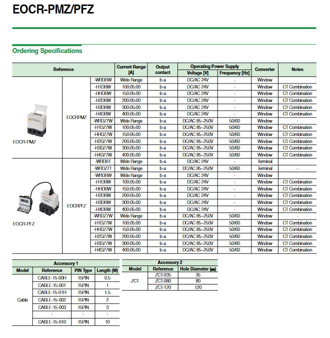
EOCR-PMZ (panel embedded) and EOCR-PFZ (embedded) motor comprehensive protector
Product positioning and types
EOCR-PMZ: perforated (Window/Hole Type), panel installation
EOCR-PFZ: Terminal Type, Panel/Rail Installation
Purpose: Comprehensive protection for three-phase motors/lines, current monitoring, and 4-20mA transmission output
Core Features (Key Highlights)
Automatic loop display
Every 5 seconds, it automatically displays in rotation: L1 → L2 → L3 three-phase current → leakage current, and can be manually locked with one click.
Integrated with full function protection
Overcurrent, undercurrent, locked rotor, locked rotor start, phase imbalance, phase failure, reverse phase, ground fault (leakage).
Wide range measurement
Body: 0.1~60A; in combination with external CT: 1~3600A.
Fault memory
Automatically save the reasons for the last 3 trips and the current at the time of the trip, without loss during power outages.
Run time management
Total running time timer (maximum 99999 hours), maintenance reminder can be set (such as bearing replacement).
4~20mA analog transmission output
For remote current monitoring, shielded cables must be used.
Optional overcurrent characteristics
Definite, Inverse, Thermal Inverse.
Ground fault (leakage) detection
Adopting zero phase current ZCT detection, supporting timed/inverse time limit.
Hot memory protection
Automatically reset the heat accumulation value 20 minutes after the motor stops.
**Fail Safe fault safety function**
Power self-test, output contact forced action in case of abnormality, switchable.
Complete protection function list
Overcurrent protection (OC)
Under current protection
Stall During Startup
Jam During Operation protection
Phase Loss Protection
Unbalance protection
Reverse phase protection
Earth Fault Protection
Secondary Functions
4~20mA current transmission output
Accumulated total running time (cannot be changed)
Preset running time reminder (can be set from 1 to 9900h)
Three reset methods
Manual reset (H-r)
Electric reset (E-r, power-off reset)
Automatic reset (A-r, 0.3s~20min)
✘ Automatic reset is not allowed for phase failure, reverse phase, grounding, and locked rotor.
Fault record query (last 3 times)
Fail Safe self diagnostic security output
Technical specifications (key parameters)
Current setting range: 0.1~3600A (body+external CT)
Main body hole type range
1 hole: 0.5~60A
2-hole: 0.25~5A
5 holes: 0.1~2A
Grounding fault current: 0.03~10A
working power supply
AC/DC 24V
AC 85~250V 50/60Hz
Output contact: AC250V 3A (resistive)
Accuracy: < 1A ± 0.05A; ≥ 1A ± 5%
Insulation: DC500V 10M Ω or above
Installation: 35mm DIN rail/panel opening
EMC: Meets IEC61000-4-2 static electricity, surge, etc
Operation and Display
Display section
5-digit 7-segment LED: displays current/time/parameters
Phase sequence indicator light: L1/L2/L3
Bar chart: Load rate (65-100%)
button
UP/DOWN: Parameter selection/numerical adjustment
SET/STORE: Set/Save
RESET: Reset
Set process
Mode → Set → Adjust → Store → Reset
Display mode switching
Auto cycle ← → Manual single display (press SET to switch)
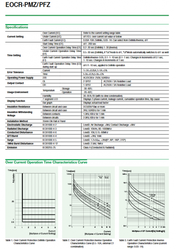
Protective action characteristics
Overcurrent characteristic
Fixed time limit (dE): current exceeds the standard → fixed time trip
Inverse time limit (In): The larger the current, the faster the trip
Thermal memory inverse time limit (th): Memory motor heating status, reset after 20 minutes of shutdown
Ground fault characteristics
Time limit/inverse time limit optional
Action Time
Adjustable from 0.1 to several hundred seconds
Trip Reason Display Comparison Table
OC: Overcurrent
Under: Undercurrent
Stall: Start blockage
Jam: Running blockage
Rev: Reverse phase
Unb: Imbalance
Loss: phase failure
EF: Grounding fault
After tripping, it can be directly viewed, and the current of each phase during tripping can also be checked.
Key points of wiring (important)
ZCT zero phase transformers must not be grounded.
4~20mA output must use shielded cables.
When used for frequency converters, it is recommended to install it on the secondary side of the frequency converter.
When starting the star delta, ZCT is installed above the main contactor and below the main circuit breaker.
When Fail Safe (FS) is enabled:
Power on → disconnect 95-96, close 97-98
Normal operation → 57-58 closed
Model and selection rules
1. Current range code
WR: Wide range 0.5~60A
H1:100:5 CT
HH:150:5 CT
H2:200:5 CT
H3:300:5 CT
H4:400:5 CT
2. Output contacts
D: Standard b-a output (95-96/97-98)
3. Working power supply
B:AC/DC 24V
Z7:AC 85~250V
4. Structural form
W: Window Perforation (PMZ)
T: Terminal Type (PFZ)
5. Accessories
ZCT-035/080/120 (aperture)
15PIN connecting cable (0.5~10m)
Applicable scenarios
Three phase asynchronous motor protection
Fan, water pump, compressor, conveyor belt
Low voltage distribution circuit current monitoring
A system that requires remote 4-20mA monitoring
Equipment that requires maintenance of timing and fault recording