Bonfiglioli EM-IO-02 Expansion Module
Overview of Hardware Resources
EM-IO-02 is a pluggable option board that can be inserted into the lower slot of the frequency converter when powered off, and automatically recognized and enabled when powered on. Hardware List:
CAN HighSpeed system bus (ISO DIS 11898, up to 1 Mbaud)
1-way bipolar analog input EM-S1INA (12 bit, ± 10V voltage/± 20mA current, switch by dialing S3)
1-way bipolar analog output EM-S1OUTA (± 10 V, maximum 2 mA, short circuit overload protection)
3-channel digital input EM-S1IND/S2IND/S3IND; Can be used as a second incremental encoder speed sensor (up to 150 kHz)
1 relay normally open output EM-S1OUTD (24V AC/DC, resistive 1A)
New: EM-MPTC motor PTC thermistor interface (DIN44081, action threshold 2.85 k Ω, also supports bimetallic normally closed contacts)
Hardware conflict reminder: If other CAN controller options (CM-CAN) are installed at the same time, the CAN bus of this module will be automatically disabled.
Terminal definition (X410A, X410B, Wieland DST85/RM3,5, tightening torque 0.2-0.3 Nm)
X410A
Pin function
1+20V output, maximum 180mA
2 20V‑GND
3 DI1 EM‑S1IND
4 DI2 EM‑S2IND
5 DI3 EM‑S3IND
6-7 relay output EM-S1OUTD (normally open)
X410B
Pin function
1-2 EM MPTC motor PTC temperature detection input
3 Analog inputs EM-S1INA
4 Analog outputs EM-S1OUTA
5 CAN‑Low
6 CAN‑High
7 CAN‑GND
Onboard dip switch S1/S2/S3
S1, S2: CAN bus terminal resistance; Passive terminal S1=ON, S2=OFF; Active terminals S1 and S2 are simultaneously turned on, and only one module is allowed to turn on the active terminal in the entire network; All products are turned off at the factory.
S3: Analog input mode: OFF=voltage ± 10 V; ON=current ± 20 mA.
Safety, storage, transportation, and installation
Safety red line: Disassembly and assembly of modules must be completely powered off and wait for the DC bus capacitor to fully discharge; Belonging to electrostatic sensitive devices, it is prohibited to touch the PCB circuit board with bare hands; Only licensed professionals are allowed to work.
Storage: Original packaging, dry and dust-proof, no electricity storage for up to 1 year; Compliant with EN50178 standard.
Mechanical installation: Remove the lower cover plate of the frequency converter, insert the module directly into the lower slot, and restore the cover plate; Ready when powered on.
Electrical wiring: It is necessary to disconnect the power and plug in the control wire; CAN bus must use braided shielded twisted pair cables; Physical isolation between power cables and communication cables; Both ends of the shielding layer are extensively connected to PE.
CAN System Bus
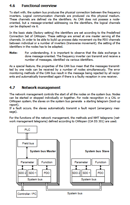
Following the CANopen CiA DS301 standard, with a linear bus topology; Support master/slave mode.
1. Key configuration parameters
900 Node – ID Node Address: -1=Bus shutdown; 0=This machine serves as the main station; 1-63 are slave stations; A single network can have a maximum of 63 slave stations and 1 master station.
903 Baud Rate (Baud Rate Maximum Cable Length)
Maximum baud rate bus length
50 kBaud 1000 m
100 kBaud 800 m
125 kBaud 500 m
250 kBaud 250 m
500 kBaud 100 m
1000 kBaud 25 m
2. Communication channel model
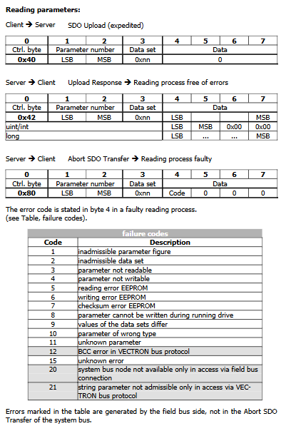
SDO channel (parameter read-write, Client Server model)
SDO1: The upper PLC/master frequency converter accesses all slave parameters and supports Profibus DP and RS232/485 transparent transmission to access all nodes on the bus;
SDO2: reserved for visual debugging tools, can be parameterized to avoid compatibility conflicts;
Only supports uint/int/long data types, string parameters are not readable or written; Use the Expedited SDO protocol.
PDO channel (real-time process data): 3 sets of TxPDO (transmit) and 3 sets of RxPDO (receive) for each frequency converter
Working mode: time triggered/SYNC synchronization message triggered;
Virtual links: Bangfeili’s custom mechanism directly maps the internal signals of the frequency converter to PDO bytes through the source number Source Number; Real time data can be directly exchanged between frequency converters without going through a PLC;
Supports one to many broadcasting, with PDO and SYNC message timeout monitoring and fault reporting when exceeded.
NMT network management: There are three states for nodes: Pre Operational, Operational, and Stopped; Only the Operational PDO process data is valid.
SYNC synchronization message: periodically sent by the master station, synchronizing all slave stations PDO;
Emergency message: The slave station automatically reports an alarm due to a fault, and the main station parameter 989 is configured to “stop” or “only alarm” upon receiving the emergency message.
3. Bus planning tool (accompanying document)
Kbl.doc: Communication Relationship Definition Table; Vvk.doc: Virtual Link Configuration Table; Load_Systembus.xls bus load calculation table; The total bus load is recommended to be ≤ 80%, and it is not available if it exceeds 90%.
The KP500 panel can only view the bus status; Advanced CAN parameters must be loaded with XPI configuration files using VPlus software.
IO Function Detailed Explanation
4.1 Analog Input EM-S1INA (12 bit)
Dial S3 to switch voltage/current mode; Can be used as a frequency setting, percentage setting, and limit source.
Four input characteristic modes: 1- Bipolar; 11- Monopolar; 21- Industrial sensor mode (2-10V/4-20mA); 101- Absolute bipolar.
Two point custom calibration: X1/Y1, X2/Y2 coordinate custom input-output mapping; Support tolerance bands, hysteresis, and low-pass filtering time constants.
Fault monitoring: configurable warning, deceleration shutdown, and free shutdown when the signal is below 1V/20mA; Hardware zero and full-scale calibration.
4.2 Analog output EM-S1OUTA
Output ± 10 V; can map analog input absolute value, actual speed and other signals; Support offset, amplification, and hardware zero gain calibration.
4.3 Digital inputs EM-S1IND/S2IND/S3IND
Universal DI: Extended fixed frequency FF5-FF8 selection;
Second incremental encoder (speed sensor 2): S2IND=phase A, S3IND=phase B, S1IND=reference mark; Up to 150 kHz; Support quadruple frequency evaluation; Can be used as an actual speed feedback source for speed closed-loop; Support encoder disconnection and phase sequence error fault alarm.
4.4 Relay Digital Output EM-S1OUTD
Single normally open relay output, software mapping the internal status of the frequency converter (running, faulty, reaching given, etc.).
4.5 EM-MPTC motor PTC thermal input (newly added in EM-IO-02, not available in EM-IO-01)
Supports DIN44081 standard PTC thermistor (action 2.85k Ω) and is also compatible with bimetallic normally closed thermal protection contacts. Parameter 570 (Operation Mode Motor Temp.) provides multiple protection modes:
Only alert;
Immediate fault shutdown (fault F0400);
Fault shutdown after a delay of 1 minute/5 minutes/10 minutes;
Trigger the rear panel to report F0400 fault, and the red fault LED lights up; The fault can be reset through the panel and digital input.
Parameter Overview
Divided into VAL (Actual Value Monitoring Menu) and PARA (Parameter Setting Menu)
VAL actual monitoring: second encoder frequency/speed, analog input%, analog output V, DI/DO status, CAN node status, CAN physical layer status;
PARA setting parameters:
AI: feature points, patterns, filtering, tolerance bands, fault behavior, calibration;
AO: Mode, offset, amplification, calibration;
DI/DO、 Second encoder: number of lines, working mode;
PTC temperature protection: protection mode selection;
Complete set of CAN bus: Node ID, baud rate, startup delay, SYNC, SDO/PDO identifiers, PDO mode, timeout, all virtual link mapping parameters.
Most of the CAN advanced parameters KP500 operation panel are not visible and can only be enabled by VPlus software through XPI configuration files.
Fault Code
IO local fault
F14-02: Analog input signal fault
F14-30: Speed sensor 2 malfunction
F14-31: Encoder phase loss
F14-32: Encoder phase sequence error
F14-33~35: Encoder line configuration error
F0400: EM-MPTC motor overheating fault (EM-IO-02 specific)
CAN system bus fault
F21-nn: Report fault from station nn;
F22-00: SYNC message timeout;
F22-01~03: RXPDO1-3 received timeout;
F22-10: Bus BUS OFF; After BUS OFF, the module automatically reinitializes the CAN bus.