Lauer PCStopline series text operation panel
Overview of Model Hardware
Model LCD display screen function buttons LED Remarks
PCS009 4 × 20 characters F1-F8 (8 pieces) 1 green LED per key Minimum model
PCS090 2 × 40 characters F1-F8 (8 pieces), green+yellow dual LED per key
PCS095 4 × 40 characters F1-F16 (16 pieces), green+yellow dual LED per key
PCS095.1 4 × 40 characters F1-F16 (16 pieces) with green and yellow dual LED printing ports for each key, 4 data storage banks bank0-3
1.1 Front panel components
LCD backlit text display screen, supporting 8 user-defined special characters;
Function F key, numeric keypad 0-9, CLR clear, ENT confirm, HLP help, directional cursor keys;
Status LED:
?: Waiting for operator input;
!: Information/Warning/Fault Activation;
ERR: Communication failure;
Each F button is equipped with LED, supporting 4 states: OFF off, ON constantly on, FLASH flashing (75% on), INVERSE FLASH reverse flashing (75% off);
Pressing a button produces a button sound; Illegal button output error prompt sound, the volume is adjusted by the back panel potentiometer.
1.2 Backplane interface and DIL dip switch (10 DIP)
Communication interface group 2
25 pin D sub: RS232/TTY current loop; Used for downloading programs and printers on PC;
15‑pin D‑Sub:RS422 / RS485, Used for PLC communication;
The communication cable needs to correspond to the PLC driver manual PCS9.xxx; Programming cable model PCS733.
Definition of DIL switch
Switch function
DIL1-4 4-channel can freely use PLC input bits, mapping W4.4-W4.7
DIL5-6 PLC driver configuration parameters, baud rate/interface mode, refer to the corresponding driver manual
DIL7 baud rate: ON=115.0kBaud; OFF=38.5kBaud
DIL8 operating mode: ON=stop maintenance mode; Normal operation must be turned off
DIL9 EEPROM write protection: ON allows writing (download project); Download completed, switch to OFF to protect data
Does DIL10 contrast allow key adjustment; After adjustment, it is recommended to lock it off
Other backboard components: reset RESET button, volume potentiometer, 24VDC power terminal, with main fuse and spare fuse; The shell must be reliably grounded, and the PE must be internally isolated from the power supply at 0V.
1.3 Mechanical and Electrical Parameters
Power supply: 24 VDC ± 20%, reverse polarity protection;
Protection: IP65 front panel (with correct installation of sealing gasket), IP20 back panel;
Temperature: Operating at 0-50 ℃; Storage -25~+70 ℃; Humidity 0-75% without condensation;
Anti vibration: 50Hz/100Hz 3g;
Storage medium: Flash EEPROM, with a minimum of 10000 erase/write cycles;
Ex explosion-proof version: must be specified when ordering, explosion-proof certification cannot be added after leaving the factory, compatible with Zone1/2;
Cleaning: Only wet cloths are allowed to wipe the panel; LCD damage prohibits contact with harmful substances inside.
Software and Development System
Configuration software PCSPRO: run MS-DOS/DR-DOS; Used for editing text, variables, menus, messages, generating data records (Data Record) and downloading them to the panel. Third party software is not allowed, otherwise the device/PLC will malfunction.
PLC driver package PCS9.xxx: For different brands of PLCs (Siemens SIE, ABB, AEG, Mitsubishi MIT, Omron OMR, etc.), each PLC corresponds to an independent driver manual, defining PLC memory mapping.
PCS809 Automux option: Siemens S5 series PLC dedicated multiplexer, solves the problem of PLC only having one PG programming port, realizing the simultaneous connection of programmer PG and PCS panel to PLC.
PCS095.1 exclusive: Offline menu (HLP+CLR combination button), which can switch between 4 independent project banks 0-3; After power failure, the bank selection is reset by the DIP switch.
Data Exchange Model: Communication between PLC and PCS Panel
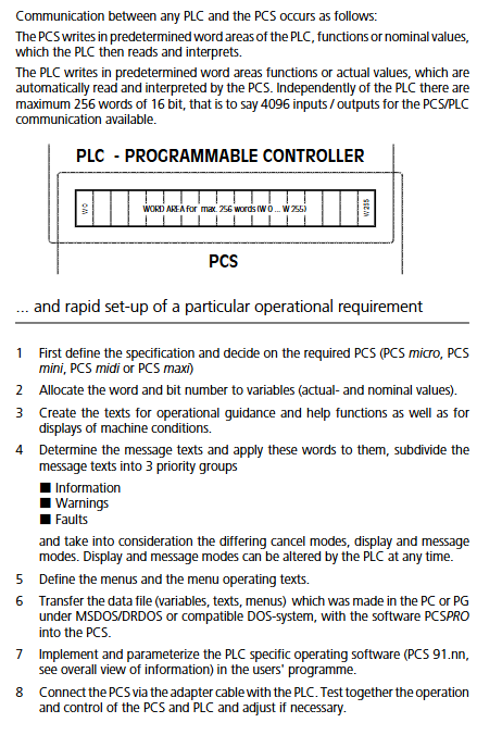
The PLC and PCS use W0-W255, with a total of 256 16 bit words for bidirectional data exchange.
PCS writes the button status and modified set values into the PLC receiving area;
PLC writes LED control words, command words, message bits, and process variables into the sending area, and PCS reads and parses them in a loop.
Communication partition
System area W0-W3: reserved internally within W0-W2; W3 communication fault word;
Functional area W4-W14: button status, panel status, LED control, command words A/B;
W4/W5: Key bits (F1-F16, numeric keys, direction, etc.) ENT/CLR/HLP);
W10/W11: LED switch, flashing status; PCS095 uses W24/W25 to manage F9-F16;
W13 [Command word A]: Priority masking, arrow LED, print hard copy, message storage mode;
W14 [Command Word B]: Standby text number, menu number, Nom-P variable permission;
Message area W15-W22:128 alarm message bits; Each bit corresponds to a message text;
Expansion area W23-W29: PCS095/095.1 is used for F9-F16 buttons LED; Try not to occupy the 009/090 version as much as possible;
Variable area W30-W255: Stores external variables (actual value Actual, set value Nominal, protected Nom-P).
Nom-P protected set variable: W14 bit7=1 allows modification; When bit7=0, it can only be displayed and cannot be modified.
Variable system (core)
Divided into internal variables and external variables; Variables are divided into three categories:
Actual value: Only panel reading display, panel cannot be modified;
Nominal setting value: readable and modifiable on the panel, confirmed and written back to the PLC;
Nominal-P protected setting value: controlled by W14 bit7 permissions.
All external variable formats
BIT bit variable: 1-bit, two types of text descriptions; Write the modification to the PLC immediately.
STRING string: Select the index for the low byte of a word, confirm with ENTER and write to PLC.
CSTRING: Same as STRING, the modification can be directly written to the PLC without the need for ENTER confirmation.
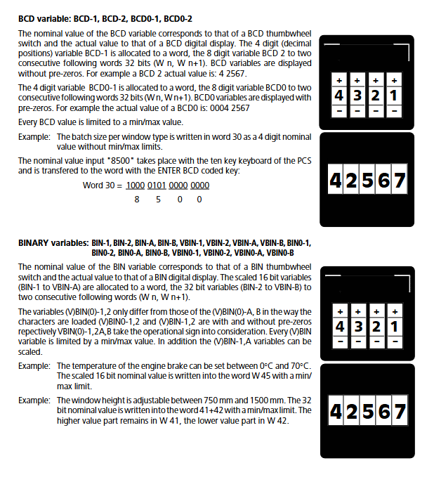
BCD-1/BCD-0-1 (16 bits, 4 bits); BCD-2/BCD0-2 (32-bit, 8-bit); BCD0 with leading zeros.
BIN/BIN0 unsigned binary; VBIN/VBIN0 signed binary; Divided into 16 bits (-1) and 32 bits (-2); A/B distinction input mode (calculator input/right push shift input); Support scaling, upper and lower limits.
WORD word variable: View and edit 16 bit words by bit, hexadecimal, byte decimal.
TIMER timer: BCD time+4 time bases, stored in one word.
ASCII characters: Multi character storage of alphanumeric strings.
Internal read-only variables (6)
ZP information message count, ZQ warning count, ZR fault count, ZT current menu number, ZV message scrolling time, ZX communication error packet statistics.
There are complete keyboard rules for editing variables: CLR restores the original value; Enter to confirm writing; Switch variables with directional keys; Some types support ± offset incremental input.
Text, menu, message system
5.1 Text Classification
Operating texts (128 entries): used for idle mode and menu pages; PCS090 2 x 40 characters per line; 009/095/095.1 Each line is 4 × 40 characters, with a maximum of multiple variables per line.
Message texts (128 pieces), maximum 32 lines; Divided into 3 message priorities:
Priority 4 Information Information;
Priority 6 Warning;
Priority8 Fault;
Help texts (5 items), press the HLP button to bring up, up to 32 lines.
5.2 Four clearing modes for messages
Mode 1 PLC clearing: PLC reset bit message disappears; The panel cannot be cleared;
Mode 2: Manually clear and reset PLC message bit: Press CLR, and set the corresponding PLC bit to 0 on the panel;
Mode 3 only clears the display on the panel, and the PLC message bit remains unchanged at 1;
Mode 4 only allows CLR clearing on the panel after the PLC sets the bit to 0.
Message display mode: first display, last display, loop scrolling display, PLC configured through W12.
5.3 Menu System
Up to 127 menus, with a maximum of 255 nodes per menu; Each node is bound with an operation text;
PLC writes W14 low byte menu number to activate menu; Write 0 to close the menu;
Jump between nodes using directional arrow keys; Arrow LED light prompt: constantly on=there are variables on the same page; Flashing=Pressing will pop up the current node;
The Nom-P variable permissions are controlled by W14 bit7.
5.4 Complete priority system (the higher the number, the higher the priority)
Priority Number Name Description
0 Default standby text is displayed when there is no higher priority
2 Menu Menu Operation Menu
4 Information message
6 Warning Messages
8 Fault message
Press the HLP key to temporarily activate the 12 Help text, which can block up to other screens
PLC command word A (W13) can mask some priorities, such as prohibiting alarms and interrupting screens when running menus.
5.5 Diagnosis and Error Warning
Power on self-test will check EEPROM verification, PLC driver existence, firmware compatibility; Display fixed English error text directly when an internal error occurs. Communication disconnection triggers ERRLED flashing and simultaneously outputs an alarm sound; After communication is restored, the PLC program must perform status verification.
PCS095.1 Unique Features
Printer RS232 interface: supports hard copy screen printing and message printing; Support XON/XOFF, RTS-CTS handshake; Printer timeout alarm can be set.
4 sets of independent project banks 0-3; Switch to offline menu through HLP+CLR; Power off reset will return to DIP switch selected bank.
Maintenance, troubleshooting, and installation points
All disassembly, assembly, and modification of DIP switches must be powered off;
When downloading the project, turn DIL9 on and turn it off to enable EEPROM write protection to prevent accidental rewriting;
DIL8 must be turned off, otherwise the panel will enter stop mode and communication with the PLC will completely stop;
The equipment must be grounded; Grounding of signal cable shielding layer;
When ordering Ex explosion-proof models, it is specified that on-site modification is not allowed to obtain explosion-proof qualifications;
Do not open the device casing; Hardware modifications result in loss of warranty.