KUKA KR IONTEC ultra series six axis heavy-duty industrial robot
Official manual for the assembly, debugging, maintenance, and repair of the KUKA KR IONTEC ultra series six axis heavy-duty industrial robot body, covering two models: KR 120 R2700 and KR 90 R2700; Support ground and ceiling installation, compatible with KR C5/KR C5-2 controllers. The manual consists of 13 chapters, including safety specifications, product descriptions, technical parameters, scheme planning, transportation, startup debugging, maintenance, repair, retirement disposal, options, appendices, and technical support.
Product Description
Robot body structure: 6-axis series articulated arm; Components: coaxial wrist (inline wrist), boom, link arm, rotating column, base frame; AC AC servo motor drive. A1-A3 is equipped with mechanical end stops for equipment protection only, and personnel protection relies on the controller’s Safe Robot safety function or optional mechanical axis limit.
Installation form: There are two installation methods: ground and ceiling, and wall mounting is not supported; The installation posture of the ceiling must be configured within the WorkVisual software. Configuration errors can cause overload and abnormal movement.
Permitted use: For handling tools and fixtures, processing/transporting workpieces, it must meet the specified environmental conditions.
Clear prohibition of misuse (loss of warranty for misuse): used as a climbing pedal, operating beyond parameters, lacking safety protection, carrying people and animals, outdoors, explosion-proof areas, radioactive environments, underground mining.
List of body options: A1-A3 mechanical shaft limit, multi version energy pipeline package, brake manual release device, A1 overtravel protection, adapter flange, insulation flange, etc.
Technical data
KR 120 R2700
The rated load is 120 kg; the maximum limit load can reach 155 kg (subject to KUKA load verification conditions); The overall weight of the machine; Repetitive positioning accuracy ± 0.05 mm; maximum reach radius 2702 mm.
Axis motion range: A1 ± 185 °; A2‑140°~+60°; A3‑95°~+171°; A4 ±180°; A5 ±125°; A6 ±350°; Attached are the maximum speed parameters of each shaft under rated load.
KR 90 R2700
Rated load of 90 kg, ultimate load of 116 kg (requires KUKA load verification); The motion stroke is consistent with the 120 model, but the maximum speed of some shafts is slightly lower.
common parameters
Wrist flange: hole diameter 125 mm; 11 M10-10.9 threads, engagement depth 15-19 mm; locating pin Φ 10 H7; provides allowable bearing force/torque for the flange.
Base foundation load: Provide vertical force, horizontal force, overturning moment, and A1 rotation moment for ground installation and ceiling installation respectively; Used for customer foundation/steel structure design.
Environmental conditions: Operating temperature range of 0-50 ℃; Storage -40~60 ℃; IP protection; Noise level is less than 75 dB (A).
Cable: compatible with KR C5/KR C5-2; The cable can be selected as 7-50 μ m, with a maximum of 50 μ m; 16 μ m ² equipotential grounding conductor.
Stop distance and stop time: Refer to the KUKA Xpert database to distinguish between Stop 0 category 0 emergency stop and Stop 1 category 1 controlled stop.
Description of the location of the body nameplate and warning label; REACH regulation information access path.
The load not only depends on the weight, but also on the center of gravity position and moment of inertia, all parameters must be checked and entered into the controller, otherwise it will shorten the service life of the gear motor. The manual comes with complete load curve diagrams for two robots.
Planning
Provide 3 base installation options, with a minimum concrete foundation grade of C20/25.
Standard Base Kit: Part Number 0000-469-134; Including base plate, positioning pin, M20 bolt, chemical anchor bolt; If the foundation flatness is insufficient, leveling mortar can be used. It is prohibited to fill the bolt hole position with mortar.
150mm raised base kit: part number 0000-474-237, used for lifting robots.
Direct installation of rack frame: directly fixed to the customer’s steel structure/slide table, relying on cylindrical pins and flat pins for positioning, and 8 M20 bolts are tightened diagonally and step by step.
Warning: There is a risk of robot overturning, and the integrator is fully responsible for the stability of the entire machine.
Cable planning requirements: minimum bending radius of motor cables ≥ 150 mm; data cables ≥ 60 mm; separate wiring for motor and data cables; Complete equipotential grounding must be done; Interface A1 is located at the rear of the robot base.
Attention to A1 axis movement: There is no mechanical hard limit at the factory, relying on software limit; Before moving A1 in the uncalibrated state at zero, the cable twist must be completely untied to prevent internal cable twisting; A1 can be equipped with mechanical overtravel protection options.
Transportation
Forced transportation posture (uniform for all models): A1 0 °; A2‑140°;A3 140°; A4 0°; A5 90°; A6 0 °. Maintain this posture throughout the entire transportation process.
Two methods of transportation:
Forklift: Use the fork slots on both sides of the base. For suspended ceiling models, only transport frames or forklifts can be used for handling after disassembly; Prohibit excessive deviation of the fork arm and damage to the fork groove.
Crane lifting: Use optional lifting equipment (part number 0000-463-537) and 3 M12 eyebolts; Dismantle tools and pipeline packages to prevent center of gravity deviation.
Avoid impact and vibration during transportation; Lifting is prohibited from using other lifting points on the main body.
Startup and Re Debugging
The complete start-up process is divided into four installation conditions: standard base ground, 150mm raised base ground, rack ground installation, and rack ceiling installation.
General installation process: Clean the contact surface → Install the positioning pin → Position the robot → Tighten the M20 bolt diagonally in multiple passes → Level (grout if necessary) → Cure the chemical anchor bolt.
Cable wiring (KR C5/C5-2)
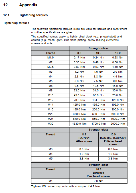
The torque of the grounding conductor M8 nut is 23 Nm;
Motor cable XD30, tightening torque 3 Nm; data cable XF31 must be fastened with a locking buckle;
Perform equipotential conductivity verification according to VDE 0100 and EN 60204-1 after wiring completion.
Complete motor cable and data cable pin allocation drawings.
A4 axis overtravel indicator: After losing the zero point, select the correct direction to run to the pre calibrated notch based on the position of the indicator pin, to avoid twisting and damaging the cables inside the wrist.
Conclusion: Install the tool, configure the robot installation posture (ground/ceiling) in WorkVisual, and run the T1 mode test.
Maintenance
Only allow the execution of maintenance items specified in this manual; The remaining maintenance work will be entrusted to KUKA certified personnel.
Maintenance cycle: The oil change cycle for all gearboxes is 20000 operating hours or 5 years, whichever comes first; Recheck the bolt torque after 100 hours of initial start-up.
Gear oil model: Optigear Synt. ALR 150; Provide oil injection volume for each axis; Distinguish the ground/ceiling posture, and before changing the oil, the robot must be moved to the designated posture with the oil outlet at the lowest point.
Maintain project list
Visual inspection of A1 cable sheath, brush with Optitemp RB2 grease;
A1-A6 gearbox oil draining, pressure relief, filling, and oil level inspection; Before draining oil, it is necessary to ventilate and release pressure to prevent scalding caused by hot oil spraying out; The torque of the oil discharge magnetic plug is 20 Nm;
Robot cleaning: Only neutral water-soluble cleaning agents are allowed, and high-pressure steam jet cleaning is strictly prohibited.
Attention: When the oil discharge is less than 70% of the nominal capacity, the gearbox needs to be flushed; Oil discharge below 50% requires multiple washings. Oil change completed T1 mode low-speed operation, check that there is no leakage at all sealing positions.
Maintenance
Includes replacement of all motors A1-A6, replacement of A1 gear input shaft, replacement of mini gauge zero calibration block, and a complete set of electrical wiring schematics.
General safety for motor replacement
Before disassembling the A2/A3/A5/A6 motors, it is necessary to use lifting ropes to secure the corresponding arm bodies; If the power failure brake fails, the arm will fall due to its own weight, posing a risk of fatal compression.
Thinly apply Microlube GL261 grease to the spline area of the new motor; The O-ring must be replaced with a new one; Do not install the motor at an angle; Tighten the bolts diagonally in stages;
After the motor replacement is completed, the axis must undergo zero point calibration mastering; T1 low-speed test.
The disassembly complexity of wrist A4/A5/A6 motors is higher: it requires draining oil, removing cover plates, connector boards, disassembling small gears, handling sealant (DreiBond series sealant), and replacing seals.
A1 gear input shaft replacement: Simultaneously replace the radial shaft seal and retaining ring.
Mini gauge replacement: A special tool is required to apply DreiBond sealant to the threads with a torque of 2.8 Nm. After replacing the calibration block, the program points may shift and need to be re taught.
Complete electrical schematic diagram: A1-A6 motor, brake, temperature sensor, micro RDC encoder, and all protective grounding circuit drawings.
Priority should be given to using KUKA original spare parts for spare parts; During the warranty period, returning faulty parts requires filling out a repair card.
Retirement, storage, and disposal
Dismantling steps: The robot moves to the standard transport posture; Dismantling tools and fixtures; Emergency stop, lock and power off; Disconnect the cable and ground it; Loosen the M20 bolt on the base, lift it vertically, and protect the positioning pin.
Storage conditions: The storage environment is dry and dust-free, reducing temperature fluctuations and preventing condensation; Storage temperature -40~60 ℃; Body cleaning and covering; Dismantling tools and additional loads.
Scrap disposal: Separate and recycle cast aluminum, steel, copper, and electrical components according to local regulations; Waste gear oil should be treated as hazardous waste.
options
Brake manual release device (only available for A1-A3, wrist motors for A4-A6 are not accessible)
Purpose: To manually move joints in case of power failure, only for emergency rescue and escape.
Key warning: After using the release device to move the joint, all axes must be recalibrated and the brake function must be tested, otherwise collision may cause injury; The release device of the suspended ceiling model cannot be fixed on the robot base, it must be fixed on the fence wall.
A1 axis mechanical overtravel protection: mechanical stopper to prevent A1 axis from exceeding ± 185 ° when zero point is lost.