KUKA Robots KR QUANTEC-2 HC Assembly Instructions
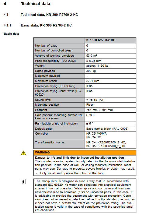
HC = Health Care, Specialized heavy-duty robots for healthcare applications; Model: KR 300 R2700-2 HC, KR 300 R2700-2 HC II, rated load of 300 kg, maximum arm span of 2701 mm; only allowed for ground installation, base allows maximum ± 5 ° tilt; Ceiling and wall hanging are strictly prohibited; Adapt controllers KR C4-HC, KR C5-M6/M7. The main body is equipped with a liquid gas energy storage balance cylinder (pressure equipment) and a Patient Rescue exclusive system, aimed at automation scenarios in the medical industry.
Product Description
Body structure: 6-axis serial robot; Components: In line hollow wrist, upper arm, connecting rod arm, rotating column, base frame, hydraulic pneumatic pressure balancing cylinder, Patient Rescue patient rescue system, complete set of micro RDC electrical components.
A1-A3 have mechanical hard stops for equipment protection purposes only; A2 Negative factory built-in mechanical limit; Personnel protection relies on the Safe Robot safety function of the controller.
Distinguishing between two major sub models
KR 300 R2700-2 HC: compatible with KR C4-HC and KR C5;
KR 300 R2700-2 HC II: Only compatible with KR C5-M6/M7, cable specifications may vary.
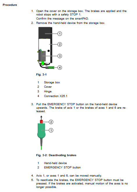
Patient Rescue Patient Rescue System (exclusive to HC models): used for mobile robots in emergency situations during power outages, and for personnel rescue in medical settings; Composed of a storage box and an emergency stop handheld device; Open the storage box and trigger STOP 1 for safe shutdown of the robot; A1 (HC-II can release A1+A6) brake to achieve manual joint movement.
Installation of rigid constraints: Only for ground installation, maximum ± 5 ° inclination of the base, ceiling/wall mounting is prohibited; The balance cylinder structure only supports ground posture, and incorrect installation may cause the arm to fall and pose a risk of death.
Permitted use: Medical related handling and tooling operations; Environmental conditions must be met.
Prohibited misuse: Climbing and trampling, overloading, carrying people and animals, outdoors, explosion-proof, radioactive environment. Misuse will result in the loss of all warranty.
Wrist flange: ISO 9409-1, flange specifications, normal operation and emergency stop impact conditions flange force torque; Reserved additional load installation interface for column/boom.
Available options: brake manual release device, various flange adapters.
Technical Data
The KR 300 R2700-2 HC/HC-II models have the same mechanical body parameters, but differ in controller adaptation and cable specifications.
Public basic parameters
The self weight of the body is about 1150 kg; the rated load is 300 kg; the maximum arm span is 2701 mm; the repeat positioning accuracy is ± 0.05 mm; the working envelope is 53.9 m ³;
Protection level: IP65 for the entire machine and IP65 for the wrist; Noise level<75 dB (A); Base 754mm × 754mm;
Temperature: KR C4 operates at 5-35 ℃; KR C5 operates at 0-55 ℃; Storage -40~60 ℃;
Cable: KR C4 maximum cable length 20 m; KR C5 maximum 50 m; 16 mm ² equipotential grounding conductor;
Mastering angles: A1-25 °; A2-100 °; A3-100 °; A4 0°; A5 0°; A6 0 °.
Foundation load
Provide normal/peak operating conditions: vertical force Fv, horizontal force Fh, overturning moment Mk, A1 rotational moment Mr; additional loads on columns and connecting rod arms are not included in the foundation load and must be added to the foundation design; The minimum grade of concrete is C20/25.
Stop distance&stop time
Distinguish between STOP 0 (category 0 uncontrolled emergency stop) and STOP 1 (category 1 controlled shutdown);
Provide A1-A3 axes under KR C4 and KR C5 controllers, as well as stop angle and stop time curves for different POV program magnifications, extension lengths, and load masses;
STOP 0 will generate high load on the robot, so try to avoid frequent triggering as much as possible; Perform brake testing at least once a year.
Other
Wrist flange axial force, radial force, overturning torque (normal, emergency stop impact); Additional load installation dimension diagram; Instructions for the nameplate and warning label of the main body; REACH and RoHS compliance information.
Planning and Design
Provide 3 sets of ground installation plans, all for ground use only:
S780 with fixed base kit (part number 0000-327-118, approximately 58.5 kg): concrete foundation; Bottom plate, positioning pin, M24 bolt, chemical anchor bolt; Leveling mortar is allowed for uneven foundations, and it is strictly prohibited to pour mortar into bolt holes; Provide the dimensions of the foundation section and the distance between the edges of the steel bars.
150mm raised base S780 (part number 0000-338-338, approximately 261kg): Raise the robot body.
Rack direct installation kit (part number 0000-310-641, approximately 3.52 kg): Customer steel structure/slide table; Cylindrical pin+flat pin positioning, 8 M24 bolts are tightened diagonally in steps.
Cable and interface planning
The external interface at the rear of the A1 base of the main body includes motor cables, data cables, Patient Rescue patient rescue cables X25/XG25, balance cylinder system cables X26/XG26, teaching pendant cables, and grounding terminals.
Complete definition of KR C4 and KR C5 connector pins; Minimum bending radius; The equipotential must meet VDE0100 and EN 60204-1.
Special requirement: The operating location of the Patient Rescue system must ensure that the operator can access it on site.
Reminder: Continuous extreme working conditions (high temperature, high frequency start stop) require a shortened maintenance cycle and consultation with KUKA services is needed.
Transportation
Mandatory standard transportation posture (unified for all models): A1 0 °, A2-135 °, A3 150 °, A4 0 °, A5 105 °, A6 0 °; The transportation posture cannot be changed.
Transportation method
Forklift: Base fork slot, minimum load capacity of 2 tons, can be forked in both directions;
Crane lifting: Special lifting equipment part number 0000-342-903; Dismantle tools and pipeline packages to prevent center of gravity deviation.
Prohibit non certified suspension points; Provide the center of gravity coordinates of the entire machine; Avoid impact and vibration during transportation.
Startup and Re Debugging
Complete start-up process for three installation conditions: standard centering base, 150mm raised base, and rack steel structure installation.
General process: Place the lifting device in place → Clean the installation surface, install the positioning pin → Position the robot → Tighten the M24 bolts diagonally in multiple stages; Necessary grouting and leveling; Dismantle the transportation lifting equipment.
Wiring specifications
Grounding M8 nut torque 23 Nm;
The tightening torque of the motor cable is 3 Nm; the data cable buckle must be completely locked;
Patient Rescue rescue cable X25/XG25 and balance cylinder system cable X26/XG26 must be connected;
The wiring is completed and a complete equipotential conduction test is performed.
Special start-up steps: Exhaust the balance cylinder, move the A2 axis ± 30 ° to release the accumulated air inside, and prevent the protective cover from popping out and injuring people.
T1 mode low-speed whole machine trial operation; Complete cable pin allocation diagram.
Maintenance
Before maintenance of HC medical models, the equipment must be decontaminated and a hygiene status statement must be provided. Maintenance beyond the scope of the manual should be handed over to KUKA certified engineers.
Maintenance cycle benchmark
5000 hours or at the latest 1 year: lubrication of balance cylinder bearings; Pressure inspection of balance cylinder system; Functional testing of Patient Rescue rescue system;
20000 operating hours or 5 years, whichever comes first: replace all gearbox oil;
The balance cylinder must be replaced as a whole after 10 years (pressure components are mandatory).
consumables
Gearbox oil: Optigear Synt. ALR 150; Lubricating grease LGEP 2 for balance cylinder bearings; The capacity manual table for each axis is provided.
Key points for oil change operation: The gearbox is in a hot working state; Ventilate and release pressure before draining oil to prevent scalding caused by hot oil splashing; Magnetic plug specified torque; Flush the gearbox with less than 70% of the nominal capacity when draining oil; Rinse less than 50% multiple times; Oil change completed T1 low-speed running in, check the seal for no leakage.
Maintain project list
Drain oil, rinse, and add oil to each axle gearbox;
Balance cylinder: pressure detection, standard pressure 176 bar (± 5 bar) bar@20 ℃); Check the corrugated pipe and seal for leaks;
Complete functional testing of Patient Rescue rescue system;
Whole machine cleaning: only neutral water-soluble cleaning agents; High pressure steam jet cleaning is strictly prohibited;
Grounding circuit continuity test, grounding resistance limit ≤ 0.1 Ω.
Maintenance
Medical application equipment must be decontaminated before maintenance; To return spare parts to the warehouse, a repair card needs to be filled out.
General safety rules for motor replacement: disassembly of A2/A3/A5/A6 motors, mechanical locking of the suspension arm, and locking of the balance cylinder at the same time; Power off the brake and balance cylinder energy storage will cause the arm to fall and squeeze to death.
Motor replacement steps: Disassemble the connector; Remove the bolts; Apply Microlube GL261 lubricating grease to the involute spline of the new motor (excessive grease is prohibited from entering the brake); Replace all O-ring seals with new ones; Do not install the motor at an angle; Tighten the bolts diagonally in stages; Restore the connector.
Motor replacement completed: The axis must be master calibrated at zero point; T1 low-speed test.
In addition to the replacement of each axis motor, it also includes the replacement of additional brakes, inline hollow wrist assembly, transmission shaft, balance cylinder cable, and the disassembly and replacement of the entire Patient Rescue system.
Complete electrical schematic: motor, brake, temperature sensor, micro RDC encoder, balance cylinder pressure sensor, patient rescue circuit, all grounding circuits.
High voltage safety 5-step procedure: power-off, locking to prevent restart, electrical inspection, grounding short circuit, isolating adjacent live parts.
Shutdown, Storage, and Scrap Disposal
Dismantling process: The robot moves to the standard transport posture; Emergency stop, lock and power off; Dismantling tools and fixtures; Disconnect the cables (including Patient Rescue and balance cylinder cables) and ground them; Loosen the M24 bolt on the base, lift it vertically, and protect the positioning pin.
Storage conditions: dry and dust-free, avoiding condensation, -40~60 ℃; Clean and cover the body, remove tool accessories, seal electrical connectors, and place desiccants if necessary.
Scrap and dismantle
Classification and recycling of cast aluminum, cast steel, steel, copper cables, and electrical components; Used gear oil as hazardous waste;
Before disassembling the balance cylinder, it must be completely depressurized. There is a risk of explosion if the internal high-pressure nitrogen gas is not depressurized;
Complete decontamination and disinfection and sterilization before scrapping medical application equipment.
Options: Brake Manual Release Device
Purpose: Manual movement of joints in case of power failure, limited to emergency rescue only;
After using the release device to move the joint, all axes must be recalibrated and the brake must be fully functional tested to prevent injury from collision.