KUKA Robots KR 1000 titan; KR 1000 L750 titan With F Variants Assembly Instructions
The product includes KR1000 titan, KR1000-F (cast version), KR1000 L750 titan, KR1000 L750-F (long arm cast version), compatible with KR C2 edition2005/KR C4/KR C5 controllers. Robots belong to semi-finished mechanical equipment, and the responsibility for overall CE, risk assessment, and system integration is entirely borne by the system integrator.
Product Description
Complete Robot System
Robot arm body, controller, smartPAD teaching pendant, connecting cables, system software, optional accessories.
Structure of Robot Arm Body
6-axis series overloaded robot, cast structure, driven by AC servo motor; A2 axis is equipped with a liquid air pressure balance system (pressure equipment), consisting of diaphragm accumulator, oil cylinder, pressure gauge, and safety valve. It is filled with nitrogen gas and hydraulic oil inside to counteract the gravitational torque of the connecting rod. Main components: base frame, rotating column, connecting rod arm, forearm, Inline hollow wrist (divided into ZH1000 short wrist and ZH750 long wrist), RDC box, MFH multifunctional shell.
F-casting reinforced variant: special heat-resistant silver coating on the wrist, special varnish for the whole machine; Inject 0.1 bar of dry and clean compressed air into the arm to establish internal overpressure and resist dust, coolant, and high-temperature splashes; Allow short-term 180 ℃ thermal shock; Gas consumption is 0.1 m ³/h.
Electrical: All motors use quick plug connectors, and the A1 interface at the back of the base serves as the external electrical interface.
Optional accessories: mechanical hard limit, mechanical shaft angle limit module, no drive release device (power off, manual release of shaft movement axis).
Designated Use and Misuse
Purpose: To transport heavy fixtures and large workpieces, and operate under rated environmental conditions.
Misuse will result in loss of warranty: manned/animal, outdoor, explosion-proof, radioactive environment, personnel stepping on the body, overload and overtravel.
Robots are semi-finished products and cannot be directly put into operation. The integrator shall complete the overall conformity declaration and CE marking.
Technical Data
Model Overview
Model Rated load Maximum load Maximum weight of the main body
KR 1000 titan 1000 kg 1000 kg 3202 mm ~4690 kg
KR 1000 titan‑F 1000 kg 1000 kg 3202 mm ~4690 kg
KR 1000 L750 titan 750 kg 750 kg 3601 mm ~4730 kg
KR 1000 L750 titan‑F 750 kg 750 kg 3601 mm ~4730 kg
General Parameters
Repetitive positioning accuracy ISO9283: ± 0.1 mm; noise<75 dB (A); Ground installation.
Protection level: IP65 for the body; F-cast wrist with IP67 rating.
Environmental conditions: operating temperature of 10~55 ℃; Storage -40~60 ℃; Environmental level 3K3.
Flange: ZH1000/ZH750, flange circle 200mm, 16 M16-10.9 bolts.
Cable: compatible with KR-C4/KR-C5; Motor cable, RDC data cable, 16mm ² equipotential grounding wire; The maximum allowable length of the cable is 50 meters, with a maximum of one extension.
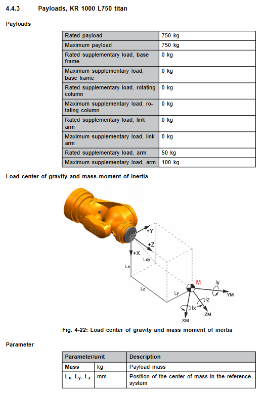
Load requirements: It is not enough to only consider the load mass. The center of gravity Lx/Ly/Lz+moment of inertia must be verified using the KUKA Load tool, and the load parameters must be entered into the controller, otherwise the gear motor will be damaged due to overload.
The maximum additional load allowed for the forearm is 100 kg; additional loads are not allowed for the column and connecting rod arm.
The axial force, radial force, and overturning moment of the flange output under normal working conditions and emergency stop peak working conditions do not include safety factors, and additional safety factors need to be added to the fixture design.
Base foundation load: output vertical force, horizontal force, overturning moment, A1 turning torque; The document values do not include safety factors, and additional safety factors must be added in civil engineering design.
Stop distance and time: Provide STOP0 (power cut-off stop) and STOP1 (path holding stop) for axes A1-A3 under KR C4 and KR C5 controllers, respectively; Charts of shutdown angles and downtime under different POV speed ratios and load ratios; The actual stopping distance of multi axis composite motion will increase; It is recommended to conduct a shutdown test on the brake at least annually.
Check the KUKA Xpert system for nameplate labels and REACH SVHC substances of high concern.
Project Planning and Design
Choose one of the two base options: a base substrate with a centering pin and a machine frame steel structure installation.
Concrete grade C20/25; Insulation layer and leveling mortar interlayer are prohibited between the substrate and concrete; It is necessary to ensure that the entire machine is resistant to overturning.
The maximum allowable inclination for substrate leveling is 3 °; Tighten with M30 bolts.
Cable planning: distinguish the specifications of KR-C4 and KR-C5 motor cables and data cables; Equipotential grounding; Cable bending radius: Motor cables ≥ 150 mm, data cables ≥ 60 mm; separate wiring meets EMC requirements.
F-casting version: planning a dry compressed air supply system, ISO8573‑1 (7:4:4), Maintain an internal overpressure of 0.1 bar.
Transportation
The robot must be placed in a standard transport posture and all external cables must be removed; Support forklift transportation, lifting with lifting equipment, and transportation frame (lowering height) in three ways.
Forklift: The base has cast fork slots, and the forklift has a minimum rated load capacity of 6 tons.
Lifting device: Use 3 specialized lifting devices with lifting ears on the body; Tools and pipeline packages must be removed to prevent center of gravity from shifting.
Transport Framework: Used for transporting height restricted scenarios, with a total weight of approximately 5600 kg.
Avoid impacts and falls throughout the entire process; Lifting operations must be prevented from tipping over.
Startup and Restarting
Base installation process
Concrete substrate: chemical anchor bolt construction, leveling; The leveling material must be completely cured.
Machine frame steel structure: positioning pin+sword pin positioning.
Robot hoisting in place, positioning pin positioning; Tighten the 12 M30 bolts diagonally in steps to 1330 Nm; after the robot runs for 100 hours, all fixed bolts must be re tightened with torque.
Cable connection: Describe the pin definitions of the KR C4 and KR C5 controller motor cables, data cables, and equipotential grounding cable connectors; The connector must be locked.
F-version put into operation: connect compressed air and adjust the pressure to 0.1 bar.
Pre operation inspection checklist: Confirm no condensation; The body has no collision damage; Connector locking; Equipotential conduction test; All safety equipment function tests.
Balance cylinder exhaust: After long-term storage, air cushion accumulates inside the balance cylinder. It must be exhausted before operation to prevent the protective cover from popping out and injuring people.
Use without a driving release device: manually release the brake to move the A1/A2 axis under power-off conditions; After completion, all axes must undergo Master origin calibration, brake testing, and T1 trial operation.
Maintenance (Power off, Lock and Tag out before Maintenance, ESD Protection)
If the oil temperature exceeds 60 ℃, the maintenance cycle must be shortened; High strength bolts must be replaced after loosening and cannot be reused.
Main maintenance projects and cycles
100 operating hours: Recheck the torque of all tightened bolts.
2000 hours or at the latest 6 months: Add lubricating grease LGEP2 to A1 main bearing; Balance cylinder pressure and appearance inspection.
Gearbox oil change: A1/A2/A3/A4/A5/A6; If the oil level is less than 70%, the gearbox must be flushed; Record the volume of oil drained as the amount of refilled oil.
A1 gear oil Optigear ALR320, initial 25L;
A2/A3/A4/A5/A6 Optigear Synt. ALR150。
A1 cable package lubrication Optitemp RB2.
Balance cylinder system: replace the entire set of components within 10 years (shortened to 10000 hours for the F-casting version); Before disassembly, the piston must be locked with a fixture, and a lifting device should be used to carry approximately 150 kg of the balance cylinder assembly; There is pressure inside the balance cylinder, and there is a risk of compression injury during operation; The complete process includes pressure relief, disassembly, and assembly.
Body cleaning: power off; Do not use high-pressure water guns or compressed air to blow the bearing seal; Clean with soft cloth and neutral detergent; Replace the damaged nameplate in a timely manner.
All maintenance is completed, and all safety functions must be retested to complete the brake test.
Maintenance
Disassembly and assembly of A1/A2/A3 large motors: The weight of a single motor is 32-44 kg; the arm of the lifting device is mechanically locked before disassembly and assembly; After reinstallation, the axis origin Master calibration must be performed.
Disassembly and assembly of A4-A6 wrist motor; Perform wrist axis origin calibration after repair is completed.
Electrical wiring instructions: MFH multifunctional housing, RDC box, complete set of motor, temperature, and encoder wiring.
If the repair items exceed the manual description, it is necessary to contact a KUKA certified engineer for execution.
Chapter 10: Discontinuation, Storage, and Scrap Disposal
Shutdown disassembly process: The robot moves to the transport position, disconnects the cables, and removes the grounding.
Long term storage: sealed interface, well protected.
Scrap: Mechanical components, hydraulic oil, and pressure components should be classified and disposed of according to local regulations.