KUKA Sunrise Cabinet Med Medical Edition Robot Controller User Manual
The user manual for KUKA Sunrise Cabinet Med, the KUKA Medical Edition robot controller, is aimed at medical device manufacturers and is used to complement LBR Med medical collaborative robots. It fully covers product overview, safety, technical parameters, planning and design, installation and commissioning, operation, maintenance and repair, troubleshooting, disposal, and appendix standards.
Product Description
Composition of Robot System
Complete LBR Med system: LBR-Med robotic arm, Sunrise Cabinet Med controller, smartPAD teaching pendant (optional), connecting cables, Sunrise. OS Med software, optional accessories.
Hardware composition of controller
The controller supports 19 inch rack installation, with main components including control PC, smartPAD control panel, wiring panel, low-voltage power unit, CCU_SR (core, including CIB_SR interface board+PMB_SR power management board), battery pack, and fan cooling system.
CCU_SR: Central power distribution and communication hub for the entire machine; Capable of safe input and output, contactor drive; When the mains power is cut off, rely on the battery to store location data and control shutdown; Equipped with diagnostic LED indicator light.
Low voltage power supply: Provides internal power to the controller, outputs 48VDC to drive the robot, and red and green LEDs indicate the working status.
Battery: After power failure, the controller is controlled to shut down, and the CCU_SR completes the charging and status detection.
Interface Description
Key interface of the panel:
X11: Safety interface (dual channel safety signals such as emergency stop, safety door, external safety stop, etc.);
X19: SmartPAD teaching pendant;
X21: Robot body interface;
X65: KUKA expansion bus;
X66: KLI external Ethernet;
X69: KSI service debugging network port;
X55: Optional external 27V DC power supply;
PE: Protect equipotential connection terminals.
Mandatory isolation requirements for external equipment: must meet IEC60601-1, 2 × MOOP/1 × MOPP, gap ≥ 3.4 mm, creepage ≥ 5.0 mm, withstand voltage 3000V; direct access to equipment requiring MOPP patient protection level is prohibited; Whole machine manufacturers need to conduct leakage current verification and system risk management.
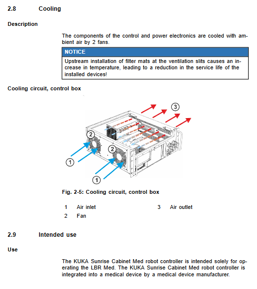
Heat dissipation
Two fans use ambient air for heat dissipation; It is prohibited to install filter cotton on the ventilation opening, as it will increase the temperature and shorten the lifespan of the device.
Designated Use and Misuse
Designated use: Only used to drive LBR-Med medical robots, integrated into medical devices by medical device manufacturers. ❌ Misuse scenarios (the library card is not responsible): industrial use, hyperparameter operation, explosion-proof environment, outdoor use, direct sterile environment use.
System design operating life: 10000 working hours.
Technical data
Basic specifications: 19 inch chassis, color medical white; Weight 23 kg; protection level IP20; Noise level is 54 dB (A).
Power supply: single-phase 110/230V AC; ± 10%; 50/60 Hz; rated 1 kVA; The maximum heat dissipation is 370 W; a protective grounding neutral system must be connected.
environmental conditions
Operating temperature:+5~+45 ℃
Storage and transportation with battery: -25~+40 ℃; Without battery -25~+70 ℃; Humidity is 5-85%.
Battery storage and charging reminder: Charge every 9 months at ≤ 20 ℃; 20-30 ℃ every 6 months; 30-40 ℃ every 3 months to prevent deep discharge from damaging the battery.
Interface electrical parameters: X11 safety input dual channel, with A/B dynamic test output; Test the output for short-circuit resistance.
Drawings: Overall dimensions of the controller, handle bracket, and optional smartPAD bracket installation hole drawings.
Nameplate label: cannot be torn off; If the manufacturer of the entire machine removes the label, it must be included in risk management.
Disclosure of SVHC list of substances of high concern under REACH regulation.
Project Planning and Design
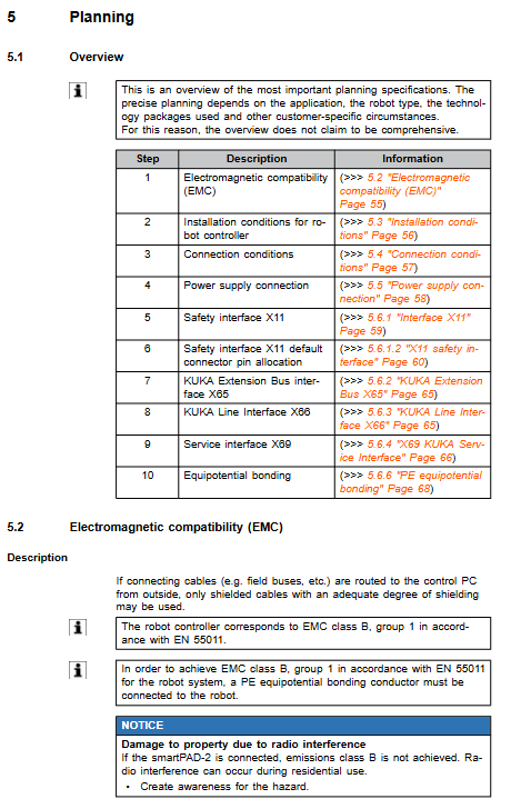
Planning process: EMC electromagnetic compatibility → installation conditions → wiring conditions → power supply → X11 safety interface → various bus interfaces → equipotential grounding.
EMC electromagnetic compatibility: The controller meets EN55011 Class B Group 1; ⚠️ Connecting to smartPAD-2 cannot achieve Class B, as residential environments may generate radio frequency interference; The cable must be shielded; PE equipotential must be done well.
Installation conditions for cabinet: 19 inch rack depth ≥ 600 mm; 70 mm ventilation reserved on both sides of the chassis; Do not install ventilation openings vertically upwards; The whole machine must be locked to prevent patients/unrelated personnel from touching it; IP20, Pollution level 2; Pollution level 3 environment requires additional enclosure protection.
Power supply: Recommended leakage protector 300 mA universal type.
Cable: The total length of the smartPAD extension cable cannot exceed 50 meters.
Key points of interface wiring
X11 safety D-SUB50 interface: dual channel safety input, TA-A/TA-B dynamic cycle test input circuit fault; Provide wiring diagrams for external emergency stop, safety door, and external safety stop; The input must use floating contacts, and external power supply is prohibited.
X66 KLI network port, X69 KSI service network port: RJ45, CAT5e Ethernet cable; X69 is used for laptop debugging and diagnosis.
X55 option: Output 27VDC up to 7A to external devices.
PE equipotential connection: It must be done, and the whole machine should undergo grounding continuity testing according to DIN EN60601-1.
Transportation
Car transportation: Close the chassis, unplug all cables, and place horizontally.
Handheld handling: Use the built-in handle of the chassis and prohibit transportation with cables; Avoid impact.
Startup debugging and re operation
Complete startup steps: Appearance inspection → Confirm no condensation → Check fuses → Install controller → Connect cables → Connect smartPAD → PE equipotential → Restore battery discharge protection plug X305 (factory disconnected to prevent storage discharge) → Configure X11 safety interface → Connect mains power → Power on → Safety device verification → Peripheral IO configuration.
The X11 plug must be unplugged and unplugged when powered off; The X305 battery plug is key, it won’t work without the backup battery plugged in. Preconditions for startup: No one or obstacles in the danger zone; All safety devices are in place; The chassis cover is closed; Temperature and environmental adaptation completed; Emergency stop reset.
Operations
SmartPAD/smartPAD-2 teaching pendant, only for integrator debugging and maintenance, prohibited for medical terminal operators to operate medical equipment.
Panel components: emergency stop button, key mode switch, enable switch (three levels), JOG jog button, start stop button, user-defined button, touch screen; The back USB port is used for backup.
Teaching pendant hot plug: Press the panel disconnect button and unplug within a 25 second window; Directly pulling without pressing the button will immediately trigger an emergency stop; After about 30 seconds of insertion, the safety device will be restored and usable; The faulty teaching pendant must be immediately removed from the system.
Maintenance
Maintenance prerequisites: Power off the controller, disconnect the power cord, lock and tag, and comply with ESD anti-static measures. Maintenance project: CCU_SR relay output inspection; Clean the chassis; Regularly replace the button battery of the motherboard, the backup battery of the whole machine, and the fan.
Cleaning: power off, vacuum cleaner to remove dust, soft cloth neutral cleaner; Prohibit compressed air from spraying water; Check and repair damaged nameplates and labels.
Repairs
All open cover repairs must disconnect the mains power supply; The device switch is not isolated from the power grid, and simply shutting it down is not enough. List of Maintenance Projects:
Dismantle the casing cover plate;
Replace the motherboard button lithium battery;
Replace the solid-state drive (SSD);
Backup batteries must be replaced in pairs, strictly distinguishing between positive and negative electrodes G3.1/G3.2;
Replace the fan component;
Reinstall the KUKA Sunrise. OS Med system software (refer to the programming manual).
Troubleshooting
CCU_SR onboard LED status definition: power light, safety node STAS1/STAS2, FSoE safety EtherCAT, link indicator light, provide troubleshooting steps corresponding to faults (check fuses, cables, replace modules).
List of fuses for each position: CCU-SR board fuse, power supply circuit fuse, DC-DC fuse, low voltage power supply unit F1/F2; There is a red LED prompt indicating that the fuse has burned out. Before replacing it, the root cause of the short circuit must be eliminated and the fuse with consistent specifications must be strictly used.
Discontinuation, storage, and disposal of scrap
Shutdown: Disconnect the peripherals, robot cables, and remove the grounding in sequence.
Long term storage: in a dry and dust-free room; Dismantle the battery and store it separately; Seal the interface and place desiccant; Regularly recharge the battery.
Scrap: Classify and dispose of electronic waste; Batteries are classified as hazardous waste and are prohibited from being discarded as household waste; The meaning of battery symbol (Pb/Cd/Hg).
Risk Management+Standard Checklist
Key Points of Whole Machine Risk Management (Responsibilities of Medical Device Manufacturers)
Aseptic environment cloth cover: cannot interfere with the robot’s movement, cannot generate additional loads, and cannot cause overheating;
Liquid intrusion protection to prevent infection and contamination risks;
The robot body is not an application component, although it meets the requirements of B-type application components, the evaluation of the whole machine manufacturer and the patient contact scenario; The controller casing is strictly prohibited from being touched by patients;
Whole machine leakage current test; Assessment of the impact of vibration on patients; Definition of fault shutdown behavior; Single fault safety requires the correct configuration of safety parameters in Workbench Med; An alarm system that complies with IEC 60601-1-8 can be built based on robot data; Network threat analysis of network access.
Reference Standards
Numerous EU/international standards: EN ISO 13849-1 (PLd Cat3), EN62061 (SIL2), IEC60601-1 Medical Electrical Equipment, EN ISO 10218 Robot Safety, EN ISO14971 Medical Device Risk Management, UL/NFPA North American Standards, Machinery Directive, MDR Medical Device Regulations, EMC Directive, etc.