KUKA Robots KR SCARA HO Assembly Instructions
SCARA-HO: HO=Sanitary Oil version 4-axis SCARA planar joint robot for the secondary food industry; Includes two models: KR 6 R700 Z170 HO, KR 13 R850 Z340 HO; only supports ground installation, not ceiling/wall mounting; Adaptation controller KR C5 micro/KR C5 micro -2; The gearbox uses food grade Cassida Fluid GL150 sanitary gear oil.
Product Description
Main structure: 4-axis SCARA robot (A1 rotation, A2 rotation, A3Z vertical lifting, A4 end rotation); Main components: base frame, connecting rod arm, boom, spindle, complete set of electrical components (micro RDC, motor cables, etc.) I/O、 Air circuit, Ethernet).
Characteristics of HO model: Targeting the secondary food industry, with optimized sealing; Support AIR0 negative pressure suction interface, which can establish a micro negative pressure inside the body to prevent dust from overflowing; Use food grade sanitary gear oil Cassida Fluid GL150.
Installation constraint: Only for ground installation, does not support ceiling or wall mounting.
Permitted use: for handling, loading and unloading, and assembly in the food industry; Environmental conditions must be met.
Misuse prohibited (loss of warranty due to misuse): Climbing and trampling, overloaded operation, carrying people/animals, outdoor exposure, explosion-proof, radioactive environment.
Body interface: Base A1 interface (motor, data, I/O expansion, Ethernet, multiple pneumatic interfaces AIR0-AIR4); Arm A2 local interface, integrated brake release button, can directly release the brake and manually move each axis when powered on.
Available options: End flange adapter kit.
Technical Data
Public basic parameters
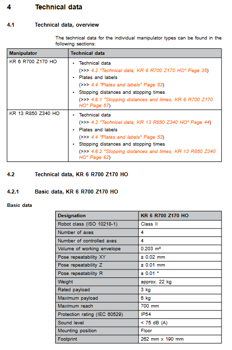
Protection level IP54; Noise KR6<75 dB (A), KR13<80 dB (A).
Operating temperature: 0-45 ℃; Storage -25~55 ℃; Low temperature start-up requires preheating and deceleration.
Compatible with KR C5 micro/KR C5 micro 2; Cable 5-25m; M4 specification equipotential grounding.
Summary of Core Parameters for Aircraft Models
Model rated load, maximum load, maximum arm span, Z stroke, body weight, repetitive positioning accuracy, XY/Z/R
KR 6 R700 Z170 HO 3 kg 6 kg 700 mm 170 mm 22 kg XY±0.02 mm;Z±0.01 mm;R±0.01°
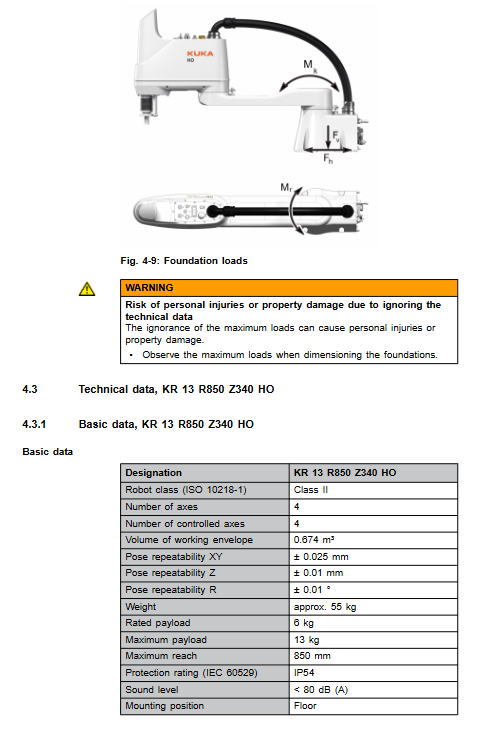
KR 13 R850 Z340 HO 6 kg 13 kg 850 mm 340 mm 55 kg XY±0.025 mm;Z±0.01 mm;R±0.01°
Complete output for each model: range of motion for each axis, maximum axis speed under rated load, load map (must be verified by KUKA software for quality, center of gravity, and moment of inertia input into the controller); Wrist flange load; Additional load is allowed on the arm; Foundation load (vertical force, horizontal force, overturning moment, A1 rotational moment); Side view/top view of the work envelope.
Stop distance and stop time
Distinguish between STOP 0 (category 0 uncontrolled emergency stop) and STOP 1 (category 1 controlled shutdown);
Provide charts of A1/A2/A3 axis stop angles and stop times for two models under different POV program magnifications, extension lengths, and loads;
STOP 0 is a reference for simulation testing; Composite axis motion will increase the stopping distance; It is recommended to conduct an annual brake performance test, and on-site testing is suggested based on actual operating conditions.
Other
Main body nameplate warning label; REACH regulation review instructions.
Planning and Design
Ground installation: Two models have different base hole positions; The minimum installation thickness of the base is KR6 ≥ 16 mm; KR13 ≥ 20 mm; concrete foundation C20/25.
Interface planning
A1 base interface: motor X30, data X31; I/O expansion X40; Ethernet X74; Multi way pneumatic connector; AIR0 negative pressure suction interface (recommended flow rate 70 L/min, pipeline outer diameter 12 mm, inner diameter 8 mm); Grounding M4 stud.
A2 arm interface: I/O expansion X41; Ethernet X94; Multi channel pneumatic; This machine comes with an onboard brake release button (powered on).
Cable specifications and pin definitions; Two reference user external cable routing schemes; Minimum bending radius of cable; Equal potential must be achieved, following VDE0100 and EN60204-1.
Transportation
Specialized standard transportation posture for each aircraft model
KR6 R700 Z170 HO:A1 0°,A2‑140°,A3 0 mm,A4 0°
KR13 R850 Z340 HO:A1‑90°,A2‑90°,A3‑100 mm,A4 0°
Handling: KR6 can be carried by two people; KR13 must use lifting devices (M10 eyebolts); Maintain the transportation posture throughout the entire process; Dismantle transportation fasteners; Avoid impact and vibration; The document provides the center of gravity and transportation dimensions.
Startup and Re Debugging
Ground installation process: Clean the contact surface of the base; Install positioning pins; Robot in position; Tighten the fixing bolts diagonally in steps (KR6: 4 × M8; KR13: 4 × M12);
Wiring specifications
Grounding M4 nut torque 2.8 Nm;
Motor cable X30; Data cable X31; Gas path connection;
Perform equipotential conduction test after completing the wiring.
Two ways to release the brake: 1) The arm body comes with a button: when the controller is powered on, press and hold the button to release the brake and manually move the shaft; 2) External Handheld Release Tool Kit: Power off status, external adapter box, select the corresponding axis to release the brake and manually move it.
After the power-off tool releases the brake to move the shaft, all shafts must undergo zero point calibration and brake testing to prevent injury from collision.
T1 mode low-speed whole machine trial operation; Complete motor and data cable pin allocation.
Maintenance
Only maintenance listed in the manual can be carried out; The rest will be handed over to KUKA certified engineers; Cassida Fluid GL150 food grade sanitary gear oil.
Maintenance cycle: visual inspection of seals and cables; Regularly check the negative pressure AIR0 exhaust system; The gearbox oil should be changed according to the official cycle;
Cleaning: Only neutral water-soluble cleaning agents are allowed; Prohibit high-pressure steam injection;
The maintenance section lists the maintenance and inspection items for KR6 and KR13 models respectively.
Maintenance
Motor disassembly: SCARA structure, arm support should be done before disassembling the motor to prevent falling; After replacing the motor, the axis must be master zero calibrated;
All O-ring seals must be replaced with new ones; Apply specified lubricating grease to the spline area according to regulations;
Includes micro RDC electrical schematic diagram; Priority should be given to using KUKA original spare parts for spare parts.
Shutdown, Storage, and Scrap Disposal
Dismantling process: The robot moves to the transport position; Emergency stop, lock and power off; Dismantling tools and fixtures; Disconnect cables, air circuits, and grounding; Lift off the body.
Storage conditions: dismantling tools; The whole machine is clean and dry; Seal all electrical and pneumatic connections; Cover with plastic cover and place desiccants if necessary; Storage -25~55 ℃.
Scrap and dismantle
Classification and recycling of cast aluminum, steel, copper cables, and electronic components; Gear oil as hazardous waste;
O-ring seals and various types of hoses are treated as hazardous waste.
Options
End flange adapter kit: KR6 and KR13 models; Including installation steps and tightening torque; After installation, check the dimensions and sealing.