KUKA TITAN-2 Ultra Ground Overloading Six Axis Robot
KUKA TITAN-2 Ultra Ground Overloading Six Axis Robot Body Assembly Manual, compatible with controller KR C5-2 L6/L7+L3EA/KR C5 L6/L7+L3EA. Model List: KR1000 R4200‑2 F、KR1250 R3700‑2 F、KR1500 R3200‑2、KR1500 R3200‑2 F; The suffix – F=Foundry casting version, supports PURGE internal pressurization blowing. Robots belong to semi-finished products (incomplete machinery), and the CE, risk assessment, and safety integration of the entire machine are all borne by the system integrator.
Product Description
Complete Robot System
Robot arm body+KR C5 series controller+smartPAD-2 teaching pendant+motor/data cable+system software+options.
Structure of Robot Arm Body
6-axis series only ground mounted overloaded robot, casting+lightweight alloy, AC servo motor; A2 is equipped with two independent liquid pressure balance systems (pressure equipment instruction class III, fluid group 2) to counteract the gravitational torque of A2 axis; The system consists of an accumulator, oil cylinder, safety valve, and nitrogen filled hydraulic oil. Core components: base frame, rotating column, left and right double link arms, boom, ZH series Inline hollow wrist, double balance cylinder assembly, double RDC box, complete set of quick plug motor and signal cables.
F-casting variant: wrist IP67; Supports PURGE pressurization option, with dry and clean compressed air flow of 0.1-0.7 MPa, 0.1 m ³/h, ISO8573-1 (7:4:4), to resist dust, coolant, and thermal splashes.
Electrical: Dual motor cable XD30/XD30.1; Data cable XF31; Base A1 integrates all external interfaces; RDCs are arranged on the rotating column and the boom respectively.
Optional accessories: A1-A3 body comes with mechanical hard limit (only for equipment protection); Optional A1-A3 mechanical angle limit; A1 hollow shaft cover; PURGE pressure regulator; No driving release device; External axis interface XG7.1/XG8.1.
The A1-A3 body comes with mechanical hard limit for equipment protection only. Personnel protection must rely on the SafeRobot safety function of the controller or optional mechanical angle limit.
Designated Use and Misuse
Designated use: for handling heavy workpieces and fixtures, for loading and unloading heavy materials, and for ground installation and use under rated environmental conditions.
Misuse will result in loss of warranty: manned/animal, outdoor, explosion-proof areas, radioactive conditions, personnel stepping on the body, overloading and overtraveling; Ceiling/wall mounted is not supported.
The ontology only provides a Declaration of incorporation; The whole machine cannot be directly put into operation. The system integrator shall complete the whole machine risk assessment, EC conformity declaration, CE marking, and whole machine operation manual.
Technical Data
Model Core Parameter Summary Table
Model: Rated load, maximum load, maximum weight, repeated positioning accuracy ISO9283
KR1000 R4200‑2 F 1000 kg 1204 kg 4218 mm ~4750 kg ±0.08 mm
KR1250 R3700‑2 F 1250 kg 1489 kg 3726 mm ~4820 kg ±0.08 mm
KR1500 R3200‑2 1500 kg 1858 kg 3226 mm ~4730 kg ±0.08 mm
KR1500 R3200‑2 F 1500 kg 1858 kg 3226 mm ~4730 kg ±0.08 mm
Protection level: IP65 for the body; F-cast variant wrist IP67; Noise<75 dB (A); Only installed on the ground.
Environmental conditions: Operating at 0-50 ℃; Storage -25~60 ℃; Environmental grade 3K3; pH 7-9; Low temperature operation requires preheating to avoid frosting and condensation.
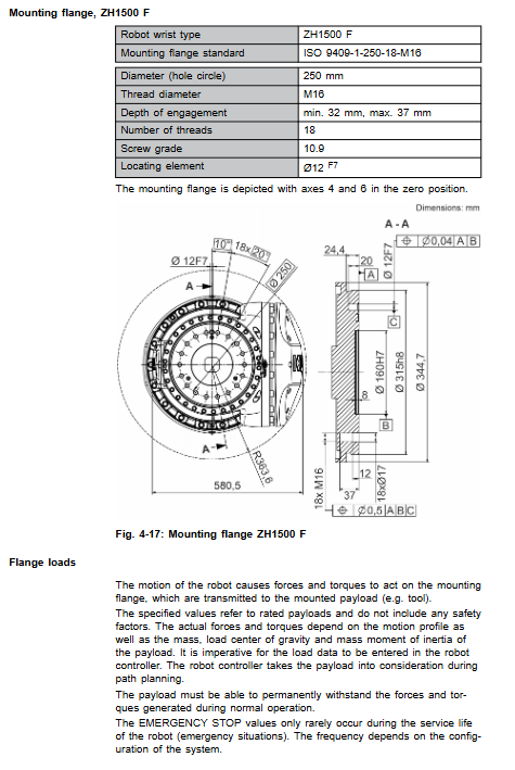
Flange standard: ISO 9409-1 series, ZH1000-2 F/ZH1500 F; bolt grade 10.9.
Cable: Dual motor cable XD30/XD30.1; Data cable XF31; 16mm ² equipotential grounding wire; ESD meets IEC61340-5-1.
Load Rules
It is not enough to only look at the load mass, it is necessary to simultaneously verify the load mass, center of gravity Lx/Ly/Lz, and three directions of rotational inertia; Using the KUKA Load tool for accounting, the load parameters must be entered into the controller; Otherwise, the gear motor will be overloaded and damaged.
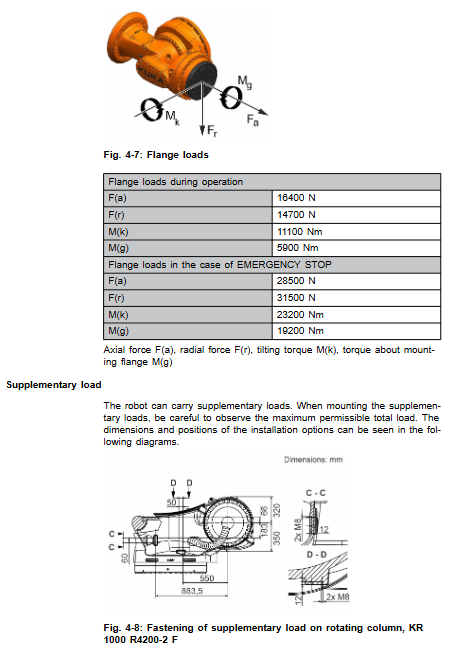
Support the installation of supplementary loads for rotating columns, left and right connecting arms, and large arms; The additional load on the left and right link arms has a total weight limit.
Flange output axial force, radial force, overturning moment, flange torque; Distinguish between normal operating conditions and peak emergency stop conditions; All values do not include safety factors; The design of fixtures and jigs must have an additional safety factor added.
Base foundation load
Output vertical force Fv, horizontal force Fh, overturning moment Mk, A1 turning torque Mr.
The values provided in the document do not include safety factors; The additional load on the rotating column/connecting rod arm needs to be manually added to the vertical load; The civil engineering design must increase the safety factor to prevent the base from overturning.
Stopping distance and time
Distinguish between Stop0 cutting off power shutdown and Stop1 path maintaining shutdown; A1-A3 axis shutdown angle and shutdown time under different POV speed ratios and load ratios; The actual stopping distance of multi axis composite motion will increase; Stop searching KUKA Xpert for detailed distance data.
Nameplate REACH
Multiple safety warning signs on the body are non removable; REACH SVHC substances of high concern information access KUKA Xpert.
Project Planning and Design
Two installation base schemes
Option 1: C1300 concrete base plate; Concrete grade C20/25; Insulation layer and thick leveling mortar interlayer are prohibited between the substrate and concrete; Use M30 bolts and chemical anchor bolts.
Plan 2: Installation of machine frame steel structure frame; Used for steel structure bases, height increasing platforms, and linear sliding tables.
The whole machine must ensure anti overturning.
Cable planning
Interface A1 (rear of base): Two motor cables XD30/XD30.1; Data cable XF31; PURGE gas supply port; External axis XG7.1/XG8.1; Grounding terminal.
Specify the bending radius of cables; EMC cabling; Requirements for equipotential grounding.
F-casting version: Planned PURGE booster gas supply system, with a gas supply pressure of 0.1-0.7 MPa.
Transportation
The robot must move to the standard transport posture specified in the manual and remove all external cables.
Handling method: Special lifting equipment for hoisting, or forklift handling (with integrated fork slots on the base); Tools with sufficient rated load-bearing capacity must be used.
Do not impact or fall; The transportation posture cannot be changed before installation on site.
Startup and Restarting
Base installation process
Concrete substrate: chemical anchor bolt construction, leveling; Robot hoisting in place, positioning pin positioning; Tighten M30 bolts diagonally in steps; After 100 hours of robot operation, all anchor bolts must be re tightened with torque.
Machine frame steel structure: positioning pin+sword pin positioning, bolt diagonal step-by-step tightening.
Wiring: Two motor cables XD30/XD30.1; Data cable XF31; 16mm ² equipotential grounding wire; The connector must be completely locked; Perform equipotential conduction test.
F-version put into operation: connect compressed air and debug PURGE pressure regulator.
Pre operation inspection checklist: no condensation; The body has no collision damage; Locking of connectors; All safety equipment function tests.
After long-term storage, air cushion will accumulate inside the balance cylinder, and exhaust operation is required before operation to prevent the protective cover from popping out and injuring people.
Maintenance (Power off, Lock and Tag out before Maintenance, ESD Protection)
If the oil temperature exceeds 60 ℃, the maintenance cycle needs to be shortened; Grade 10.9 high-strength bolts must be replaced after loosening and cannot be reused; Maintenance has been completed and all safety functions have been retested.
100 hours (only once during initial operation): Recheck the torque of all base fastening bolts.
2500 hours or 6 months: A1 cross roller bearing with lubricating grease LGEP 2; Lubrication of dual balance cylinder bearings; The frequent short stroke swing condition of A2 axis shortens the maintenance cycle to 3000 hours.
2500 hours or 1 year: visual inspection, pressure inspection, and leakage inspection of the balance cylinder; Hydraulic oil Hyspin ZZ46.
Gearbox oil change (10000 h/20000 h for different models, latest 5 years)
A1 input level: Optigear ALR320; A2-A6 gearbox: Optigear Synt. ALR150.
Oil recovery; If the oil level is less than 70%, the gearbox must be flushed; Record the oil discharge volume as a reference for refilling.
10 years: Mandatory replacement of the entire double balance cylinder assembly.
A1 cable package lubrication Optitemp RB2.
Body cleaning: power off, neutral cleaning agent with soft cloth; Prohibit high-pressure water guns from blowing seals; Replace the damaged nameplate in a timely manner.
Maintenance
This manual only describes limited disassembly and assembly operations; Repairs beyond the scope of the manual must be carried out by KUKA certified engineers.
Mechanical locking arm of lifting device before motor disassembly and assembly; After replacing components such as motors, gearboxes, cables, etc., Mastering origin calibration must be performed.
The balance cylinder belongs to the pressure component, and it should be depressurized and mechanically locked before disassembly and assembly.
ESD anti-static requirements; High strength bolts must be replaced with new parts when loosened.
Discontinuation, Storage, and Scrap Disposal
Shutdown disassembly: Move to standard transport posture; Disconnect all cables; Loosen the base bolts and lift off the body.
Long term storage: body cleaning; Seal all electrical connectors; Cover with dust-proof film and place desiccant inside; The storage environment is dry and dust-free, avoiding temperature difference condensation.
Key point of scrapping: The pressure relief of the balance cylinder must be completed before scrapping; Hydraulic oil, lubricating grease, motors, castings, and electronic components shall be classified and recycled according to local regulations.
Options
A1 hollow shaft cover: textile material dust cover; Only dustproof, without increasing IP protection level; Maintenance can only be done by dry brushing, water washing is prohibited.
PURGE Boost Option (- F Cast Version): Install pressure regulator on the A1 interface board of the base; Compressed air parameters ISO8573-1 (7:4:4), pressure 0.1-0.7 MPa, air consumption 0.1 m ³/h.