KUKA KR C4 extended is a high-power multi axis control cabinet
KR C4 extended is a high-power multi axis control cabinet that supports up to 16 axes; CK stands for Customer Kinematics. Customers can customize kinematics without the need for a KUKA body and directly drive the KUKA motor/MGU motor gear unit. Compared to the regular KR C4, this model focuses on enhancing its multi axis expansion capability, supporting a large number of external axes, positioners, palletizers, and Titan heavy-duty robots. Targeting engineers with professional backgrounds in electrical engineering, robotics, and Windows.
Product Description
Complete set of robots: robotic arm+KR C4 extended control cabinet+smartPAD teaching pendant+cables+software+options.
Core Hardware
KPC Control PC: Mainboard D3076-K/D3236-K/D3445-K; Responsible for human-machine interface, program editing, path planning, driver control, communication, and security monitoring.
KPP KUKA power pack: rectifies AC to generate DC intermediate circuit voltage, supplies power to various servo units, integrates brake chopper, multi power version, and panel LED status indication.
KSP KUKA servo package: servo driver, multiple peak current specifications, performs motor field oriented torque control.
CCU cabinet control unit (CIB cabinet interface board+PMB power management board): complete machine power distribution, internal bus communication, safety IO, fan temperature monitoring; Main contactor control, Mastering origin test; Power outage relies on battery storage location and controlled shutdown.
SIB Security Interface Board (Standard SIB/Extended SIB Expansion Board)
Standard SIB: 5 secure inputs, 3 secure outputs.
Extended SIB: 8 secure inputs, 8 secure outputs; Used for SafeRobot and SRM axis interval monitoring options, it must be used in conjunction with standard SIB.
RDC rotary transformer digital converter: collects up to 8 axis rotary transformer positions and motor temperatures; EDS storage origin and configuration; Support cascading multiple RDC boxes to achieve a 16 axis system; Divided into regular versions, without low-temperature RDC-Cool.
CSP controller system panel: Run/Sleep/Auto LED indicator lights, USB, KLI/KSI service network ports.
Low voltage power supply unit, backup battery pack, power filter.
Bus classification KCB/KSB/KEB
KCB internal controller bus: KPP, KSP, RDC, CIB;
KSB safety bus: CIB-SION, smartPAD-SION, SIB;
KEB expansion bus: Profibus, DeviceNet, EtherCAT, digital/analog IO expansion modules, with a large number of configuration variants.
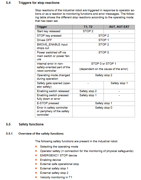
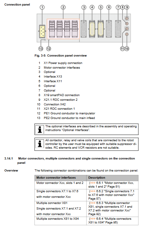
Key constraint of interface panel: Choose between discrete safety interface X11 and Ethernet safety interface X66 (PROFIsafe/CIP Safety), they cannot be enabled simultaneously.
Cooling system: dual circuit cooling; The heat exchanger cools the electronic control, and the external fan directly cools the KPP/KSP radiator and brake resistor.
Optional accessories: smartPAD bracket, roller assembly (only for short distance movement inside the cabinet, long-distance transportation is prohibited); Reserved customer option installation rails and mounting plates for the cabinet.
Permitted use and prohibited misuse
Drive KUKA robotic arm, linear unit, positioner, and customer customized CK mechanism compliant with ISO10218-1;
Prohibit high-altitude trampling, operation beyond parameters, explosion prevention, and underground mining.
Technical Data
Machine parameters: maximum 16 axes, maximum weight of 240 kg, protection level IP54; The noise is about 65dB (A);
Environmental conditions: working temperature, storage temperature, altitude derating (>1000m, power reduction of 5% per 1000m); Vibration impact index;
Mechanical dimensions: overall appearance of the machine, ground mounted openings, technical cabinet/welding cabinet compatible openings; Swing angle of cabinet door; Minimum maintenance gap;
Electrical parameters: power supply, fuse, external 24V PELV power supply specifications; Maximum length of cable;
Teaching pendant parameters; Nameplate warning label; REACH SVHC substance information;
Safety performance: EN ISO13849-1 Cat.3, PL d; PFH failure rate data.
Planning and Design (Pre System Integration)
EMC electromagnetic compatibility: Shielded cables are used for external cables, and the shielding layer is extensively crimped with PE bars; Belongs to Class A industrial equipment.
Installation conditions: independent floor standing or parallel installation of cabinet groups; Reserve maintenance gaps;
PE equipotential mandatory requirement: robotic arm ↔ 16mm ² cable between control cabinets; Control cabinet body to distribution cabinet PE row 16 mm ².
Motor connector (core of this chapter)
The document contains a massive number of wiring combinations, covering standard 6-axis, heavy-duty, palletizing, Titan robots, and supporting 3-16 axis configurations; Includes X20, X7 series single connectors, X81/X82 multi axis combination connectors, all pin assignments, and servo module correspondence.
X20 series: main mechanical arm motor;
X7 series: single external axis;
X81/X82 multi axis connector, supports combination expansion, up to 16 axes;
Titan heavy-duty robot specific X20.1/X20.2/X20.3 connector;
RDC boxes support cascading, and the length difference of the Resolve cable between multiple RDC boxes is ≤ 10 μ m.
X11 Discrete Security Interface (50 Chip D-Sub)
Dual channel dynamic pulse test TA-A/TA-B;
External emergency stop, safety door, external enable switch;
Attached schematic diagram: external emergency stop wiring, safety door+confirmation button wiring, safety floating contact input wiring;
The safety gate must be equipped with a confirmation button outside the fence, and it cannot automatically reset and run when closed.
X66 Ethernet safety interface: PROFIsafe/CIP Safety, SafeOperation option, byte bit definition, enable switch schematic.
CIB board EtherCAT interface X44/X65.
System modification prerequisite: To replace the hard drive, replace the board, add or delete devices, the system must be reconfigured using WorkVisual software.
Transportation
Three types of handling methods: lifting with lifting rings, forklift, and pallet handling; The optional roller component only allows for short distance rolling inside the cabinet and prohibits long-distance dragging and transportation.
Transportation prerequisites: Power off, remove all cables, close cabinet doors, place upright, and install anti tipping brackets.
Lifting: 4 M10 lifting rings, required angle of lifting equipment, and incorrect inclined lifting is prohibited;
Forklift: standard base or dedicated fork slot, prohibit rough fork entry;
Roller: The ground must be flat and obstacle free, with a risk of tipping, and vehicle dragging is prohibited.
Startup and Re Debugging
Complete power on process:
Check for transportation damage and confirm the minimum maintenance gap;
PE equipotential wiring;
Lay motor cables and X21/X21.1 RDC data cables, following the cable bending radius; Separate the wiring of motor cables and data cables;
Install the smartPAD bracket and plug in the smartPAD teaching pendant;
Release the battery discharge protection plug; Harting X1 connected to the main power supply;
Plug in X11 or X66 safety interface in power-off state;
Clear the dangerous area of personnel and objects, release the emergency stop, close the switch and turn on the power;
After hardware/device changes, WorkVisual performs system configuration; Enable Start up startup mode as needed;
Complete functional verification of safety equipment.
Equipment Operation
Explain the buttons on the smartPAD/smartPAD-2 teaching pendant panel; Procedure for inserting and removing teaching devices;
After unplugging the teaching pendant, the emergency stop of this machine fails; Reconnect and wait for about 30 seconds. The emergency stop and third gear enable switches must be retested.
Maintenance
Maintain general safety prerequisites: power off and lock, disconnect the incoming power supply; Wait for the intermediate circuit to discharge for 5 minutes; ESD anti-static throughout the process; Do not blow compressed air directly into the cabinet.
maintenance cycle
Annual: SIB/Extended SIB relay output function inspection; Complete functional testing of all emergency stop and enable switches; Clean the fan and radiator according to the dirt condition;
5 years (three shifts operation): motherboard button battery, PC fan, and replacement of internal and external cabinet fans;
Replace the pressure relief plug (pressure relief filter plug) immediately if it changes color; If there is a battery failure alarm, replace the battery pack.
Maintenance content:
SIB relay output test: local emergency stop, operator safety confirmation, peripheral enable output, alarm interval output, SafeOperation status output;
Whole machine cleaning: Soft cloth+solvent-free cleaning agent, no water spraying is allowed;
Maintenance completion inspection: fuses, plugs, grounding, cable wear, component fastening.
Maintenance and Replacement
Maintenance can only use KUKA original spare parts; High strength 10.9 screws must be replaced after disassembly and cannot be reused. Each component provides: safety prerequisites, tools, step-by-step disassembly and assembly, connector definition, torque, and final functional testing. List of replaceable parts:
External fan, internal fan module;
KPC controls the entire set of PC, PC fan, motherboard button battery, HDD/SSD hard drive, and dual port network card;
KPP power pack, KSP servo pack; ⚠️ After replacing KPP/KSP, wait for 5 minutes for the intermediate circuit to discharge, and the heat sink of the shell should be high-temperature to prevent burns;
CCU cabinet control unit;
SIB standard security board, Extended SIB extended security board;
RDC rotary to digital converter;
Battery pack (divided into two installation positions behind the cooling air duct and inside the cabinet door, must be replaced in pairs, pay attention to polarity, and prevent short circuits);
Low voltage power supply unit; Pressure relief filter plug; Braking resistor; Power filter;
KSS system software installation instructions;
Important: Hard disk replacement and hardware module replacement require WorkVisual to reconfigure the system.
Troubleshooting
CCU board LED indicator lights: power supply, bus, safety node, fuse LED, different flashing colors/frequencies correspond to fault phenomena and countermeasures;
List of all CCU fuses: number, rated current, purpose, with red LED indication for fuse melting;
Interpretation of LED status on RDC and CSP system panels;
LED status of network ports on each motherboard (D3076-K/D3236-K/D3445-K);
SIB/Extended SIB safety board LED, safety position;
KPP and KSP servo module LED status;
Complete KPP/KSP error code table (260xx): overload, ground fault, overcurrent, intermediate circuit overvoltage and undervoltage, logic power supply fault, overtemperature, motor phase loss, communication fault, braking resistor fault; Each one contains the cause of the malfunction and the corresponding handling measures;
KPP/KSP warning message list.
Shutdown, Storage, and Scrap Disposal
Shutdown and return: Disconnect all peripherals, motor cables, and grounding wires to prepare for transportation;
Long term storage: indoor dry and dustproof, avoiding condensation; Remove the battery and seal the interface casing for protection; Regularly recharge the battery according to temperature (≤ 20 ℃ every 9 months; 20-30 ℃ every 6 months; 30-40 ℃ every 3 months);
Scrap and disassembly: classified by material; Waste batteries are returned to suppliers for recycling as hazardous waste, and the disposal of household waste is prohibited.