LTI‑Motion ServoOne Field Bus Systems PROFIBUS and PROFINET
Equipment Introduction
PROFIBUS-DP: RS-485 physical layer, master-slave architecture; DP-V0 cyclic process data, DP-V1 non cyclic parameter read and write; Does not support real-time IRT.
PROFINET IO: Ethernet TCP/IP; Support real-time RT, IRT, etc; Supports both circular and non circular access.
PROFIdrive V4.2: PI organization drives equipment standards, unifying control words/status words, messages, and operating modes to achieve interoperability between controllers and drivers of different brands.
Hardware installation, interfaces LED、 topology
3.1 PROFIBUS-DP interface (X14, 9-pin D-Sub socket)
Three ways to set addresses
After modifying the address, the drive must be restarted for it to take effect.
Single axis/multi axis ServoOne: dip switch S1/S2; When dialing to 0xFF, software parameter modification address P-0918 is allowed;
All models: DriveManager software parameter P-0918-COM_SP_Address;
Drive local seven segment digital panel settings.
LED status lights H1 (yellow)/H2 (red)/H3 (green), different flashing codes represent: self-test, search baud rate, waiting parameters, cyclic data exchange, configuration error, DP-V1 non cyclic connection status.
D-Sub pins: 3=B (red), 8=A (green), 5=DGND, 6=VP+5V (bus terminal power supply); Terminal resistors must be enabled at both ends of the bus segment.
Topology: Bus type is predominant; The use of repeaters can achieve tree structure; Each network segment can have a maximum of 32 nodes.
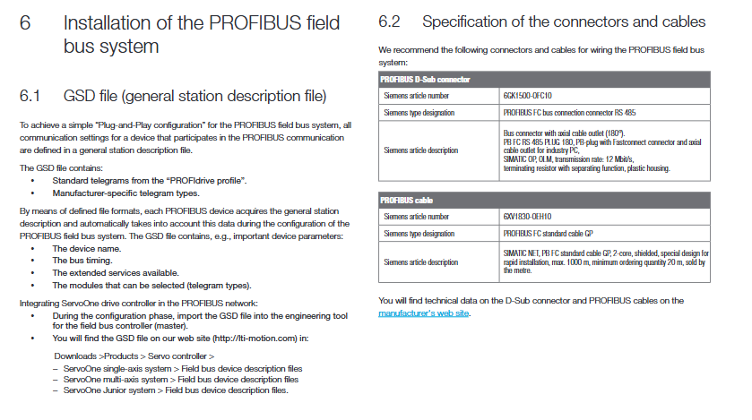
Configuration import: Import GSD device description file.
3.2 PROFINET interface (X47, X48, dual RJ45)
Dual network ports support Auto Negotiation and Auto Crossing automatic crossing; No need for crossover cables; Each RJ45 comes with a link/activity LED and a RUN status LED.
Topology: Supports line type, star type, tree type, and ring network MRP.
Configuration import: Import GSDML XML device description file and select DAP2 device access point.
Support real-time RT-Class1, IRT, etc; PROFINET supports device names IP、 Subnet and gateway parameters.
Cable selection suggestions
PROFIBUS: Siemens 6XV1830-0EH10 standard DP cable, 12Mbaud;
PROFINET: Cat5e industrial shielded Ethernet cable, 6GK1901-1BB10-2AA0 metal shell RJ45 connector.
Cyclic data communication
PPO = Parameter‑Process‑Data‑Object, Divided into two parts:
PZD (Process Data): Real time loop, control word, set value, actual value;
PKW (parameter channel): Read and write drive parameters in loop mode (optional, not all PPOs come with PKW).
4.1 Standard PROFIdrive message
The purpose of the message number is applicable to the bus
STD-1 Application Class 1, Speed Control 2-Word Input/2-Word Output DP/PN
STD-2 speed control, 4-word input/output only PROFINET
STD-3 IRT equal time real-time speed control, application class 4 only PROFINET
STD-5 DSC dynamic servo control (position, IRT), application class 4 only PROFINET
STD-7 driver set selection mode DP/PN
STD-8 interpolation mode positioning, application class 5 only PROFINET
STD-9 positioning mode, target position+positioning speed DP/PN
Note: Some functions of STD-2/3/5/8 are only supported by PROFINET IRT and not by PROFIBUS-DP.
4.2 User defined message (manufacturer PPO)
Select which signals to map to the PZD channel using parameters P-1284 (write signal list), P-1285 (read signal list), and then P-0915/P-0916;
P-0922 Select PPO message type; Up to 32 read-write signals can be mapped, supporting word/dword;
Some PPOs have built-in PKW loop parameter channels, which can read and write driver parameters during loop bus cycles.
4.3 PKW parameter channel (cyclic mode parameter read and write)
PKW structure: PKE task ID+PNU parameter number, SUB sub index, LEN length, Data data;
Task ID (AK): Read parameters, write Word, write double characters, read parameter descriptions, read and write strings, etc;
The driver returns a response ID, including success/error codes; Define a complete error number table, such as illegal parameter numbers, limit violations, sub index errors, etc.
4.4 Bus monitoring function
Watchdog (P-1283 COM_SP_BUS_Timeout): detects loss of bus loop messages; Timeout triggers fault 32-1; Set=0 to turn off the watchdog.
Sign of Life (SOL life signal, PROFINET only): The master station outputs an up counter in bit 12-15 of control word 2 (STW2), and the slave station verifies synchronization; Parameter P-0925 is set to allow error threshold, with an over limit alarm of 32-03; Used for real-time synchronization verification in IRT and other applications.
Non cyclic communication
PROFIBUS-DP-V1 (SD2 message) and PROFINET Record Data are used for non periodic reading and writing of driver parameters, without occupying the PZD cycle.
Base Mode Parameter Access: ROFIdrive standard non cyclic access format; Supports one-time read and write of multiple parameters, including parameter descriptions, arrays, and strings.
Message structure: Request reference number, task ID, axis number, parameter number PNU, sub index, format, numerical value; Provide a complete request response example.
Extended diagnosis: The driver can upload internal fault and warning numbers to the controller through bus diagnostic messages; Configurable diagnostic modes (standard/extended/vendor customized diagnostics).
PROFIdrive V4.2 Operating Mode and State Machine
6.1 Drive complete state machine (8 system states)
0 initialization → 1 not ready → 2 prohibit closing → 3 ready closing → 4 close and power on → 5 enable operation → 6 activate quick stop → 7 fault response → 8 fault. The status jump is initiated by the main control word STW1 (P-0967), and the driver returns the status word ZSW1 (P-0968); There is also a second control word STW2 and a second status word ZSW2.
STW1 key bit:
Bit0: Power level closing/opening
Bit1: Inertial shutdown
Bit2: Quick Stop
Bit3: Controller Enable
Bit4: Slope generator reset
Bit5: Slope Enable
Bit6: Set value activation edge
Bit7: Fault Confirmation
Bit8-9: Jogging JOG1/JOG2
Bit10: PLC control permissions
Bit11: Zero Return Trigger
Bit12-13: Positioning mode (absolute/relative, edge triggered mode)
ZSW1 driver status word: feedback driver status, fault, target arrival, zero return, tracking error exceeding limit, warning bit, etc.
Quick Stop has 7 options with code P-2218, which can be configured for behaviors such as free sliding, slope deceleration, limited flow emergency stop, and keeping enabled after stopping.
6.2 Supported PROFIdrive application categories
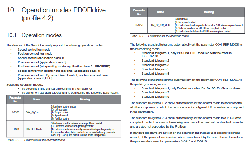
AC1 speed control: STD-1 message; Slope function generator RFG processing speed setting.
AC3 position control (configuration generation mode): The driver generates trajectories internally and issues target positions, speeds, and acceleration/deceleration.
AC5 interpolation positioning mode (PROFINET): The controller directly issues real-time position settings, and the driver only performs closed-loop without generating internal trajectories.
AC4 isochronous real-time IRT
Speed mode (STD-3);
DSC dynamic servo control STD-5: The main station directly issues position error XERR and position loop gain KPC, high-performance motion control, commonly used in Simotion.
6.3 JOG Jog Mode
Two modes: manufacturer customized JOG/PROFIdrive standard JOG, switched by parameter P-1267 bit8; Both jog speed and acceleration/deceleration can be mapped to bus parameters.
6.4 Returning to Zero Homing
Two ways to return to zero:
Drive local zeroing: STW1 bit11 triggers zeroing; Return to zero and complete the zero point marking of ZSW1.
Controller controls zeroing (Touch probe probe): using digital input ISD05/ISD06 probe signals; G1-STW sensor control word, G1_ZSW sensor status word; P-1255 configuration probe input and edge; Read the position of G1_XIST1/G1_XIST2 encoder.
P-0979 sensor format parameters: read-only, the driver is automatically generated from the encoder configuration, describing the encoder type, resolution, shift factor, and multi turn absolute value range.
6.5 Scale/Unit Conversion
Three factor groups: STD/402 (DSP402), SERCOS, User defined; Configurable in USER mode: encoder resolution, numerator denominator (mechanical transmission ratio), position/velocity/acceleration units, exponent, scaling factor, converting the bus received in engineering units (mm, °) to internal incremental units of the driver; Provide a complete example of angle unit configuration.
Debugging configuration case
Case 1: User defined message, position control (configuration generation mode PG)
Import GSD/GSDML into engineering software and select the corresponding PPO message;
Set drive parameters:
P-0300 CON_CfgCon=3 position control mode;
P-0301 CON-REF_Mode=0 configuration generation mode (internal trajectory of the driver);
P-159 MPRO_CTRL_SEL=7 PROFIBUS/PROFINET as control source;
P-0915 (write PZD mapping): Map STW1, target position, positioning speed, acceleration and deceleration;
P-0916 (Read PZD Mapping): Maps ZSW1, actual position, and actual velocity;
Download parameters, bus control start stop positioning.
Case 2: User defined message, speed control
P-0300=2 speed mode; P-0301=0 slope generation; Control source selection bus;
PZD mapping control word, speed setting, acceleration and deceleration; Feedback status words and actual speed.
The manual lists all mappable bus parameter lists P-1284/P-1285, including control words, status words, position, speed, torque, limit, probes, etc.
Bus parameter summary table
Key parameter excerpt:
Parameter Number Parameter Name Description
P-0918 COM_SP_Address Bus Station Address
P-0922 COM_SP_TelegramSelection PPO message type selection
P-0915 COM_SP_PZDSelectionWrite PZD Signal Selection List
P-0916 COM_SP_PZDSelectionRead PZD Read Signal Selection List
P-1283 COM_SP_BUS_Timeout bus watchdog ms, 0 closed
P-0925 COM-PN_Sign_of_life_imit SOL life signal allowable error count
P-0967 COM_SP_Controlword STW1 main control word
P-0968 COM_TP_Status Word ZSW1 Driver Status Word
P-1274 COM_SP_RefPos Position Setting (Interpolation Mode)
P-1275 COM_SP_Target Pos Target Position (PG Mode)
P-1276 COM_SP_ActPos1 actual encoder position
P-1278 COM_SP_ACC acceleration
P-1279 COM_SP_DEC deceleration
P-0944~P-0952 fault memory group stores the last 20 fault codes and fault numbers
Technical Specifications
PROFIBUS-DP: up to 12MBaud, automatic baud rate recognition; The maximum bus length is related to the baud rate; DP-V0 cycle, DP-V1 non cycle; Only do from the station.
PROFINET IO:100Mbit; RT/IRT; Minimum cycle of 500 µ s; supports MRP ring network; IO devices.
Glossary of terms: PPO/PFD/PKW/DP-V0/V1/V2, IRT, RFG ramp generator, DAP, DO driven object, Watchdog, Sign of Life, etc.