Micro Innovation MICRO PANEL GS-2 Industrial Touch Visualization Operation Panel (HMI)
Product Overview
Core hardware components: GS-2 body+SMM system memory module (rear can be plugged and unplugged)+communication expansion board (slot type, such as MPB-TP multi protocol board).
Software: PDT software for PC, used to develop HMI project screens, downloaded to SMM module.
Important Disclaimer: This HMI cannot implement personnel or equipment protection safety functions; The manufacturer shall not be liable for any related losses caused by malfunction or damage; The document parameters are not legally guaranteed, and the technical specifications may be changed without notice.
Version: Document version 01, released on December 15, 2003.
Mechanical installation
2.1 Dimensions of external openings
Overall dimensions of the machine: 312 × 222 × 76 mm; weight approximately 3.5 kg
Cabinet opening: 296 × 194 mm; M5 fixed screw hole.
Display: 9-inch EL electroluminescent screen; The viewing angle is greater than 160 °.
2.2 Installation Requirements
Leave a minimum of 5cm of heat dissipation gap between the equipment and other components on the top, bottom, sides, and back; The heat dissipation and ventilation joints must not be obstructed by cables or objects.
Working conditions: Vertical installation, smooth air convection; Altitude ≤ 2000 meters.
IP65 front panel protection: Additional installation kit needs to be purchased (not included in the standard supply); The kit includes a rear compression frame to ensure that the sealing gasket is tightly pressed against the thin control cabinet panel in order to achieve IP65.
Interfaces, hardware buttons, and indicator lights
backplane interface
Power supply terminal (3-pole plug-in terminal): 24VDC; PE protection ground, 0V.
Allowable voltage: 20.4~28.8 VDC; Ripple limit 18.5-30.2 VDC; Typical current consumption is 0.9A.
Two system power LEDs:+12V and+5V power status indicator lights.
ROG-PORT (9-pin D-Sub male, isolated RS232 programming port)
Purpose: PC download project; SMM-2 version can output logs through an external serial printer.
Pin 2=TxD, 3=RxD, 5=GND; 9-pin+5V (only allowed for use with original accessories, external third-party devices are prohibited from taking power); Shell shielding.
DOWNLOAD button: triggers the download system interface.
Slot: Pluggable communication board (MPB-TP, etc.).
Download cable
PC and PROG-PORT connection download project; Two D-Sub female heads, 2-6 pins connected 1:1 directly.
Only temporarily connect to the computer during debugging and downloading, the cable can be unshielded; When the equipment is running normally and the cable is retained, shielded copper braided cable must be used.
SMM system memory module
SMM is a tool free pluggable module at the back of the device, fixed with two rolling screws, storing operating system POS and Flash project engineering. SMM can only be disassembled and assembled in a power-off state, and touching the contacts with hands is prohibited to prevent ESD static damage.
Differences in Model, Specification, and Function
SMM-1 Standard Version Flash 128KB Basic HMI Screen Function
SMM-2 Enhanced Flash 512KB Multilingual; Larger image and text storage space; Support the recording of logs by the external serial port printer of PROG-PORT
SMM module comes with a WRITE-ENABLE write enable toggle switch
Normal operation: It must be turned off to disable writing and prevent accidental rewriting of the project.
Download project/rewrite project: Turn on to allow writing to Flash.
Be sure to switch back to OFF after downloading is complete.
Specification for Cable Manufacturing and EMC Shielding
To achieve the EMC index of the document, it is necessary to strictly follow the cable handling:
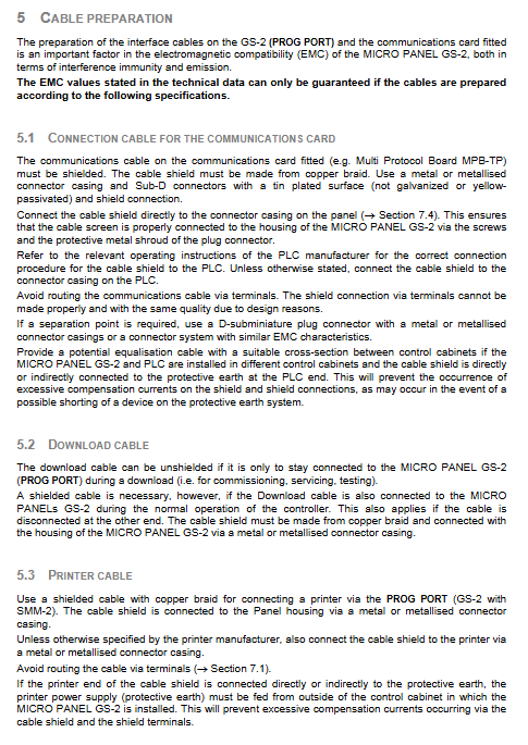
Communication board cable: must be a copper braided shielded cable with a metal shell D-Sub connector; The shielding layer is extensively crimped onto the metal shell of the joint, and it is prohibited to use only the terminal to crimp the shielding layer.
Cross control cabinet installation (HMI and PLC are different cabinets): Equipotential connection wires must be laid to avoid large compensation currents flowing through the shielding layer.
Printer cable (SMM-2): Copper braided shielding, metal joints at both ends grounded; The printer PE and HMI cabinet PE need to come from different power supply circuits.
Standard processing technology for shielding layer
Wire stripping; The shielding braided layer is shortened by about 3cm;
Fold the weaving layer outward and cover it with the outer sheath; Folding part of heat shrink tubing package; Retain 5-8mm exposed shielding;
Use a metal D-Sub connector with cable crimping clamps to firmly press the folded shielding layer and achieve low impedance shell grounding.
Built in system interface
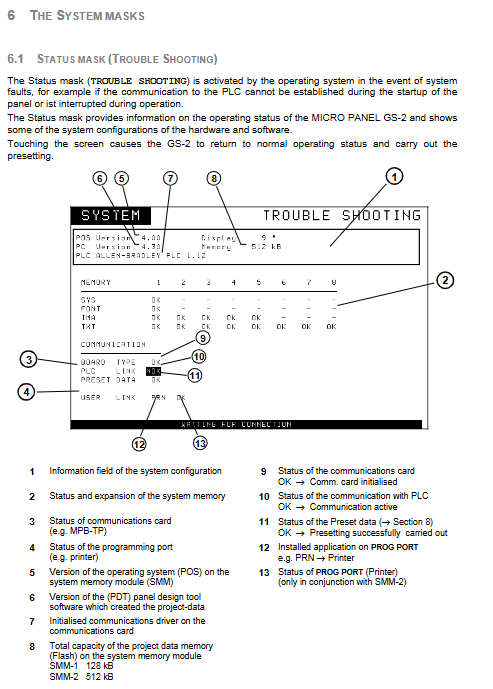
6.1 Status (TROUBLE SHOOTING) fault diagnosis interface
The system automatically pops up, commonly caused by communication failure during startup of PLC or communication interruption during operation. Interface information:
POS operating system version, PDT engineering software version;
Memory partition status SYS/FONT/IMA/TXT;
Communication board status, PLC link status (OK/NOK), preset data status;
PROG-PORT (printer) status; Touch any position on the screen to exit the diagnostic interface and return to the project screen.
6.2 DOWNLOAD (PROJECT UP-DOWNLOAD) download interface
Press the DOWNLOAD button on the backboard to enter. Function: Project upload/download, set system clock; Display hardware version, memory capacity, and transfer block count.
Transfer Active flashes, indicating that it can receive PC downloads.
Start transmission with the START touch button; EXIT exit interface.
Complete steps for whole machine debugging and operation
Turn SMM module WRITE-ENABLE to OFF; Confirm that the hardware configuration of the communication board is correct.
Connect 24VDC power supply in power-off state, do not connect PLC communication cable for now.
Turn on the 24V power supply, run the system self-test, and load the built-in demo project.
A few seconds later, the TROUBLE SHOOTING fault diagnosis page pops up, and at this time, PLC LINK=NOK is considered normal (PLC not connected); Confirm that all Memories are OK; touch the screen to exit the diagnostic page.
Press the DOWNLOAD button to enter the download interface.
Set SMM’s WRITE-ENABLE to ON (allow writing projects).
PC-GS2 connection download cable; Open the PDT software on the PC.
Press START on the HMI download interface; Transfer Active flashes, PC executes project download.
Download completed, HMI automatically restarts, self checks again.
Be sure to turn WRITE-ENABLE back to OFF!
Connect the PLC communication cable; HMI automatically establishes PLC communication; The PLC LINK status changes from NOK to OK.
Touch the screen to execute the preset, enter normal operation, and debugging is complete.
Communication board firmware upgrade Comboard Loader
Condition: HMI operating system POS version ≥ 5.01; The communication board supports Flash firmware.
Power off, unplug the communication board; Board jumper J7, switch from RUN to PRG programming mode; Insert the card back in.
Connect the ROG-PORT to the PC using a download cable; Run the COMLOAD. EXE loading tool on the PC.
Power on GS-2; The red light on the communication board is on, and the green light flashes 4 times per second before turning off. The HMI automatically enters the COMBOARD Loader upgrade interface.
PC issues firmware bin file; The flashing green light indicates normal packet reception;
Upgrade completed, power outage; Switch the board jumper back to RUN mode and reinstall the board; Upgrade completed.
The firmware version can be viewed on the DOWNLOAD system interface.
Compliance and Technical Parameters
CE EU compliance: meets EMC Directive 89/336/EWG, low voltage 73/23/EC;
Launch standard EN50081-2; Anti disturbance EN50082-2; Safety standard EN60950.
Display: 9-inch EL electroluminescence, 640 × 400; 70Hz refresh rate.
Operate infrared matrix touch, 39 × 25 touch channel.
Interface: The communication board supports TTY, current loop RS232、RS422、RS485; ROG-PORT isolates RS232, with a maximum baud rate of 9600 and a maximum cable length of 20 meters.
Environment: Storage -40~75 ℃; Anti vibration and impact meet the IEC68-2 series standards;
Protection: The front panel of the entire machine is IP65 (an additional installation kit is required).