SIGMATEK AKM series servo motor
Product Overview
1. Series coverage range
AKM is divided into 7 machine base specifications AKM1-AKM7, flange 40-188 mm, locked rotor torque M ₀ range 0.18 Nm~53 Nm, covering low-voltage 24/48 V and AC 230/400/480 V power supply versions.
AKM1: flange 40 mm, 0.18-0.41 Nm
AKM2: flange 58 mm, 0.48-1.42 Nm
AKM3: flange 70 mm, 1.15-2.88 Nm
AKM4: flange 84 mm, 1.95-6.0 Nm
AKM5: Flange 108 mm, 4.7-14.4 Nm
AKM6: flange 138 mm, 11.9-25 Nm
AKM7: flange 188 mm, 29.4-53 Nm
2. Hardware infrastructure
Rotor: neodymium iron boron permanent magnet, electronic commutation, brushless design; The stator is equipped with a PTC thermistor (operating at 155 ° C) for winding overheating protection, which must be monitored on the driver side.
Feedback encoder (order selection, factory assembly, cannot be installed later)
Standard: Rotary Transformer Resolver
Optional: EnDat (single lap/multi lap), Hiperface (single lap/multi lap SKM36).
Brake (optional): 24 VDC spring brake, power-off brake; Only for static holding, cannot be used for safety braking; Vertical loads must be additionally equipped with external mechanical brakes; Installing a brake will increase the total length of the motor and slightly reduce torque in some operating conditions.
Protection level: IP65 for connectors with sealing rings; IP54 without sealing ring; Insulation level F; Vibration level A (DIN EN 60034-14).
Bearing lifespan: standard ≥ 20000 operating hours; Bearing noise needs to be monitored every 2500 hours, and any malfunctions must be replaced by the original factory. Unauthorized disassembly will result in loss of warranty.
3. Model coding rules
Model string disassembly: machine base number rotor length winding type flange standard shaft type feedback unit brake connector shaft seal.
Flanges: IEC/NEMA, etc; Axis: flat key axis/keyless axis;
Feedback: Resolver, EnDat, Hiperface;
Brake: 2=with 24V brake, N=without brake;
Connectors: corner connectors, Y-tec IP65 connectors, etc; Shaft seal is optional.
Safety, transportation, storage, and maintenance
1. Applicable personnel
ESD electrostatic protection training is required for transportation; Mechanical installation requires mechanical technicians; Electrical installation requires electricians; Professional personnel familiar with driving technology are required for power on debugging.
Important safety points:
The motor housing must be reliably connected to the PE protective ground; It is strictly prohibited to plug or unplug the motor/feedback plug while it is live; After the drive is powered off, the DC bus capacitor will maintain high voltage for several minutes, and the DC bus voltage must be measured to drop to<40 V before contacting the wiring.
The temperature of the motor casing during operation can be greater than 100 ° C, and it can only be touched after cooling to below 40 ° C.
The key strip at the shaft end must be removed before operation to prevent injury caused by centrifugal force.
Prohibited for use in explosion-proof environments, corrosive/conductive dust and vapor environments; It cannot be directly connected to the mains power and must be used in conjunction with Sigmatek servo amplifiers.
2. Transportation&Storage
Transportation temperature -25~+70 ℃; Storage -25~+55 ℃; Humidity 5-95%, no condensation allowed;
The original foam carton is used, and the stacking height is limited; Unlimited storage life; Avoid impact, especially protect the output shaft.
3. Maintenance and repair
If the bearing reaches 20000 hours or produces abnormal noise, send it to the factory for replacement; Users are strictly prohibited from disassembling the motor body, as disassembling it will directly void the warranty;
The outer shell can be wiped with isopropanol, and soaking or spraying the motor is prohibited.
Key points of mechanical installation
Installation standard IM B5 flange installation, supporting V1/V3 vertical installation; When installing the V3 axis downwards, it is necessary to prevent liquid from seeping into the bearing.
Axial end load: strictly follow the radial force FR and axial force FA speed relationship curve of each model; To calculate the minimum pulley diameter for synchronous belt transmission, excessive radial load can significantly shorten the bearing life.
Priority should be given to using seamless elastic expansion sleeve/metal bellows couplings for couplings; Do not strike the shaft or flange; Use shaft end threads for the installation and removal of pulleys/gears, and do not strike them.
Ensure ventilation and heat dissipation; Altitude>1000 m requires power derating, with greater derating at higher altitudes (up to 55% derating at 5000 m); If the ambient temperature is above 40 ℃, the rating also needs to be reduced.
Electrical installation
Both motors and feedback must use Sigmatek prefabricated shielded cables; The cable capacitance has an upper limit (power<150 pF/m, feedback<120 pF/m), and the cable length is limited by the driver.
The power cable and feedback cable should be laid separately, with a recommended spacing of more than 20cm; both ends of the shielding layer should be grounded with a large area of low impedance.
The manual provides 4 complete sets of wiring schematics:
Resolver M23 plug; Resolver Ytec plug; EnDat encoder; Hiperface encoder.
The connector is divided into two parts: power connector and feedback connector; The number of contacts varies among different machine bases (AKM1-2 has 6 pins, AKM3 has 8 pins, and AKM4-7 has 10 pins).
Start debugging and troubleshooting
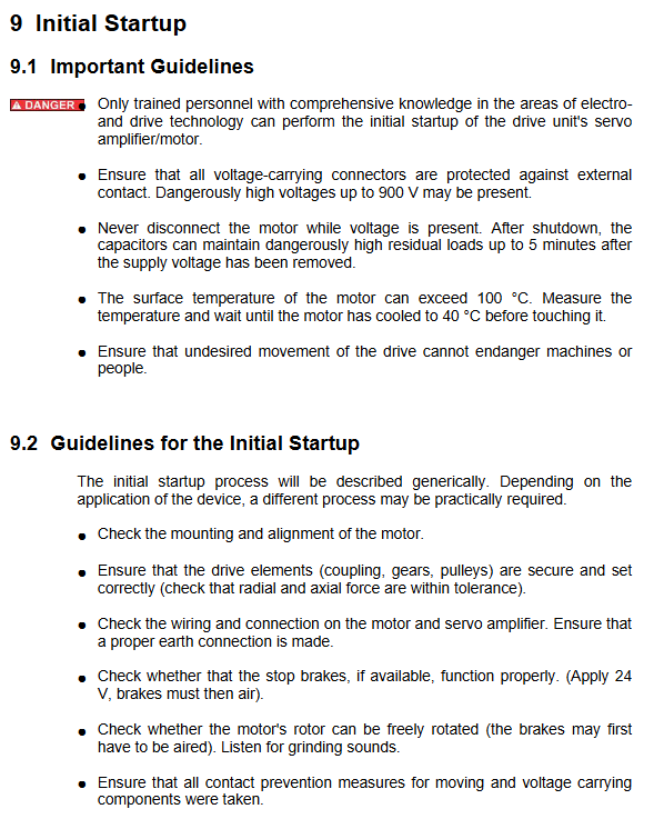
Pre-power check
Mechanical: coupling, load, confirm that the rotor can be manually rotated;
Electrical: PE grounding, cable shielding, holding brake can be released when powered on; All joints are locked;
Eliminate safety risks and prevent accidental shaft rotation from injuring people.
Common Fault Quick Check Table
Possible causes and solutions for the fault phenomenon
Motor not turning, driver not enabled, command disconnected, phase sequence reversed, brake not released, mechanical jamming check enable signal, wiring, brake, mechanical mechanism
Motor flying car motor phase reversal correction power phase sequence
Motor vibration feedback shield damaged, driver gain too high, check cable, restore driver default parameters
Brake error, brake power short circuit, brake damage, troubleshooting short circuit, replace motor if necessary
Power level fault, power cable short circuit, motor winding short circuit, replace cable or motor
The fault plug of the Resolver encoder is not locked, and the cable is damaged due to compression. Reconnect the plug and replace the feedback cable
Temperature alarm PTC overheating triggered, feedback connector loose, shutdown cooling, troubleshooting overload, checking connector
Brake failure to engage, insufficient brake torque, brake damage, review and selection, replace motor
Most vibration issues related to regulation belong to driver parameters. Please refer to the servo amplifier software help documentation.
Technical parameters
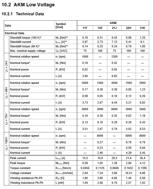
The document divides the parameters into: AKM low-voltage version (24/48/75/160 V), AKM1~AKM7, each machine base independent chapter, and each machine base sub chapter includes:
Electrical parameters: locked rotor torque M0, rated torque Mn, peak torque Mmax, current, torque constant Kt, back electromotive force Ke, winding resistance and inductance;
Mechanical parameters: rotor inertia, weight, allowable radial/axial force, static drag torque, thermal time constant;
Brake parameters: brake torque, voltage, power consumption, and suction/release time;
Cable specifications;
Continuous torque speed curve and peak torque speed curve (red solid line=continuous, red dashed line=peak) under different power supplies of 230V, 400V, and 480V;
Outline dimension drawings;
Speed radial/axial load curve chart.
Parameter note: With brake, non Resolver feedback, and shaft seal options, there will be a slight torque derating, and corresponding derating values will be provided for each machine base.
Cable
Define the model coding rules for motor power cables and feedback (sensor) cables, including the number of shielded cable cores and wire diameter specifications; If the cable length exceeds 20 meters, consultation with Sigmatek’s application department is required.