SIGMATEK TAE 1941 Touch Display Unit
Product Overview
TAE1941 is a 19 inch industrial remote touch display used for automation process visualization, operation, and status monitoring; The screen is SXGA 1280 × 1024 LED backlit TFT; The input medium is an analog resistive touch screen.
Overall appearance: 462 × 360 × 57 mm; including mounting bracket, the weight is approximately 7 kg.
Installation: Embedded installation of control cabinet panel; Front panel protection IP54, back panel IP20.
Core hardware parameters
1. Display screen
Project parameters
Screen specification 19 “TFT-LCD SXGA, resolution 1280 × 1024
Color depth of 24 bits, 16.77 million colors
Pixel size 0.294 × 0.294 mm; effective display surface 376.3 × 301.1 mm
Backlight LED backlight; The brightness decays to 50% of the original after 50000 hours in a 25 ℃ environment
Typical brightness/contrast ratio is 300 cd/m ²; Contrast ratio 2000:1
Viewing angle is 89 ° in all directions (CR>10)
2. Touch unit
Type: Analog resistive glass touch screen; The effective touch area is consistent with the display area; No physical buttons.
3. Electrical specifications
Power supply: DC 24 V (18-30 V DC allowed)
Current: Typical 1.45 A, maximum 2 A, current varies with external USB load; There will be a short-term surge current at the moment of power on.
Interface:
HMI Link G2 (RJ45): Remote video, touch, USB composite signal input;
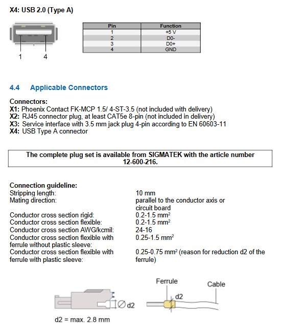
Front panel: USB 2.0-A;
Backboard: USB 2.0-A;
4-pin Phoenix Terminal: 24V power input;
3.5mm four core maintenance and debugging port (only original factory specific cables, cannot be wired by oneself).
4. Environmental and mechanical tolerance
Working temperature: 0~+50 ℃; Storage -20~+60 ℃;
Humidity: 10-90%, condensation is strictly prohibited;
EMC: EN 61000-6-2 (anti-interference), EN 61000-6-4 (radiated emission) industrial grade;
Vibration: EN 60068-2-6; Impact: 15 g (150 m/s ²), 18 impacts;
Protection level: front panel IP54, back panel IP20.
5. Front panel status LED (red and green dual color indicator lights)
Meaning of red light (LED1) and green light (LED2) status
Always on/off HMI Link physical connection disconnected, check the network cable
Flashing off, the network cable is connected, but there is no video signal. Check the backend display output
Always on, HMI Link link is normal, but there is no USB signal
Turn off the constant light system and it is ready to work normally
HMI Link G2 (Second Generation) Ethernet Cable Specification
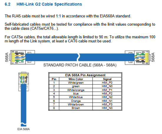
Physical medium: Shielded CAT5e/CAT6 Ethernet cable, EIA 568A line sequence, 1:1 straight through Ethernet cable, cross line prohibited.
CAT5e: maximum 90 meters; CAT6 and above can reach a full range of 100 meters.
Mandatory shielding requirement: Both ends of the shielding layer of the network cable must be grounded with low impedance to suppress interference.
Parallel laying of multiple HMI Link cables can cause crosstalk. The manual provides limitations on the number and length of parallel cables
CAT5e/CAT6: up to 6 at 30m, up to 4 at 50m, up to 2 at 70m, and only 1 at 100m;
CAT6A/CAT7: Up to 6 parallel wires of any length.
Power on initialization sequence: The TAE terminal must be powered on and connected to the HMI Link network cable before starting the backend controller/IPC, otherwise the terminal cannot initialize properly.
Replacing TAE panels with different resolutions during operation: The backend IPC/controller must be restarted to recognize the new screen parameters.
The first generation HMI Link device of G1 is completely incompatible with the hardware version of G2 and cannot be mixed.
Wiring and grounding, ESD anti-static points
Grounding: The equipment must be grounded with low impedance and large area through the installation of flanges or grounding terminals to ensure EMC anti-interference. High frequency noise is discharged through the grounding shell. The two ends of the HMI Link network cable shielding layer are grounded.
ESD electrostatic protection: USB peripherals (keyboard, USB flash drive, mouse) are mostly unshielded and highly susceptible to electrostatic interference; Before plugging or unplugging the USB, the operator touches the cabinet ground to release static electricity from the body.
Connector specifications:
X1 power supply: Phoenix FK-MCP 1.5/4-sT-3.5; Wire cross-section 0.2-1.5 mm ²;
X2: RJ45 shielded crystal head;
X3 repair port can only purchase Sigmatek original factory specific cables, third-party cables may damage the equipment.
Order number for complete connector kit: 12-600-216.
Chemical resistance of touch screen
The touch panel can withstand media such as coal tar/toluene, trichloroethylene, acetone, alcohol, gasoline, engine oil, ammonia water, glass cleaner, mayonnaise, tomato sauce, wine, salad oil, vinegar, etc. After contact, it should be wiped promptly without damage.
Touch screen cleaning standards
Before cleaning, be sure to turn off the power to prevent accidental triggering of the operation;
Spray the cleaning agent on a soft cloth and do not directly spray it onto the surface of the equipment to avoid liquid infiltration into the gaps;
Permissible: anti-static foam, neutral detergent aqueous solution, alcohol;
Prohibit grinding materials, highly corrosive solvents, and hard scraping objects;
Wipe immediately if contaminated with corrosive media; Suggest finger operation to extend touch life and regular cleaning.