Aerotech Ndrive CP Compact PWM Digital Servo Driver
Product Overview
1.1 Model and Electrical Parameters
Model Peak Current Continuous Current Remarks
CP10 10A 5A
CP20 20A 10A
CP30-S 30A 10A with built-in 40W discharge resistor – S
Power supply system: Control power supply and motor power supply with two independent AC inputs (85-240VAC, 50/60Hz); Motor busbar 20-340VDC; PWM switching frequency 20kHz; The maximum bandwidth of the servo loop is 2500Hz, and the efficiency is 85-95%.
Supporting motors: brushless AC servo, brushed DC, two-phase stepper motor.
Protection mechanism: output short circuit, peak overcurrent, RMS overcurrent, bus overvoltage, overheating, control power undervoltage, power stage bias undervoltage; Control side and power side optocouplers+transformers are isolated.
Environmental conditions: working temperature of 0-50 ℃; Storage -30~85 ℃; Humidity ≤ 80% RH (non condensing); Maximum altitude of 2000m; indoor use, pollution level 2.
Mechanical: standard weight 1.63kg; M4 screw installation; Reserve 25mm ventilation space around the driver and 100mm operating space on the cable side.
1.2 Onboard standard hardware resources
Communication: Dual FireWire (J101/J102); No RS232 debugging port.
Feedback: J103 main feedback 25 pin D-SUB; J104 auxiliary 26 pin D-SUB auxiliary encoder.
IO onboard: 4-channel optocoupler digital output, 4-channel optocoupler digital input; 2-channel 50ns high-speed differential input; 1 channel 16 bit differential analog input ± 10V; 1 channel 16 bit analog output ± 10V; onboard 24V/1A solid-state relay used for motor brake.
PSO: Only single axis PSO position synchronous output; ⚠️ Key limitation: The MXU encoder multiplier option and PSO function are mutually exclusive and cannot be enabled simultaneously.
1.3 Ordering Options
Function Description of Options
IO expansion IO board; 16 isolated DI/16 isolated DO; 1 channel of 12 bit analog input, 1 channel of 16 bit analog output; Mechanical brake relay
MXU sine cosine analog encoder interpolation, up to x 1024 (x 4096 after orthogonal); No frequency doubling signal output, prohibit simultaneous use with PSO
Equipped with a 50 Ω discharge resistor (standard for CP30, optional for CP10/20)
EXTSHUNT external discharge resistor interface TB104, without built-in – S; used for high inertia and high regenerative energy systems
The CP series does not support DUAL/TRUPLEPSO, ENET Ethernet, RDP rotary transformers, which are exclusive to HP/HLe.
1.4 Compliance Certification
Meet CE requirements (EMC 2014/30/EU, LVD 2014/35/EU, RoHS2); TUV-SUD NRTL safety certification UL61010-1.
Important safety warning: After power failure, the internal of the drive can maintain dangerous high voltage for several minutes; The working temperature of the discharge resistor can be greater than 70 ℃; High temperature of the shell; All wiring operations must be completely powered off; The whole machine integrator is responsible for the system grounding and emergency stop safety circuit.
Installation and hardware wiring configuration
2.1 FireWire Device Address Settings
Dial S1 to set the unique device number 1-32 for the driver, which corresponds one-to-one with the A3200 axis number; Support daisy chain networking; Copper cable has a maximum length of 4.5m and requires fiber optics/repeaters for long distances; Accessories include NFIRE-PCI/PCIE network cards and fiber optic FireWire cables.
2.2 Power terminals
TB106 control power supply (85-240VAC): maintains power supply for logic, communication, and encoder; After the emergency stop cuts off the motor power supply, the power supply does not cut off, achieving keep alive.
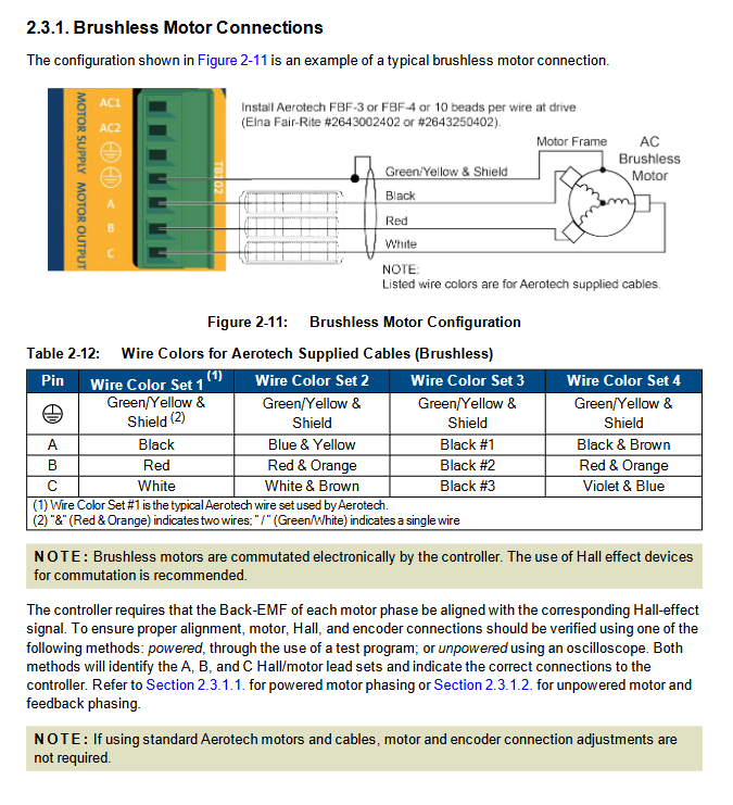
TB102 motor power supply AC input+motor three-phase output A/B/C; External delay fuses are required and must be reliably grounded for protection.
Transformer scheme: TV/TM series isolation transformer, capable of obtaining 40/80/160/320VDC DC bus; One TM3/TM5 transformer can simultaneously supply power to multiple CP drivers.
EMC wiring mandatory: Motor cables must be shielded; Power cables and feedback signal lines are physically separated; Install UFM-ST power filter on the AC side; Add corresponding specifications of ferrite magnetic rings to motor cables; CE compliance requires the final complete machine to undergo EMC testing.
2.3 Motor wiring and phase setting
The manual provides wiring for brushless, brushed DC, and stepper motors, including original cable color codes; Third party motors must be phase modulated.
Brushless servo motor
Two methods of phase modulation: ① The MsetDebug software program is used for live phase modulation; ② Power off oscilloscope measures back electromotive force and Hall timing.
Hall A/B/C connected to J103; Hall all 0 or all 1 is a Hall fault; Real time observation of Hall state using Nstat diagnostic software.
Brushed DC motor: connected to terminals A and C; B is vacant; Measure the polarity of the back electromotive force of the manual motor to determine the phase, and reverse adjust the A/C.
Two phase stepper motor: connected to A-B C; Encoder optional, phase verification is required when an encoder is available.
2.4 J103 main feedback 25 pin D-SUB connector
Integration: Main encoder (TTL RS-422/MXU analog sine and cosine), Hall sensor, PTC motor thermistor (>1k Ω triggers overheating fault), encoder fault input, CW/CCW positive and negative limits, Home reset switch, and brake output; Onboard+5V/500mA power supply for encoder and limit.
Support: TTL differential encoder, EnDat and other serial absolute encoders;
Limit support for normally open/normally closed software configuration; Reverse the limit connection will result in ‘can hit the limit but cannot retract’, switch the CW/CCW pins;
The motor thermal PTC input is used to detect motor overheating.
2.5 TB101 ESTOP emergency stop detection input
Only the signal detection port does not constitute a safety cut-off circuit in itself! Input 5-24V; only report fault status; The true safety cut-off must be achieved by cutting off the AC power supply to the motor through an external relay; Control the power supply TB106 to maintain uninterrupted power. It is necessary to enable ESTOP fault in the axis parameter FaultMask; Relay coils require RC/varistors to absorb surges.
2.6 J104 Auxiliary I/O (26 pin D-SUB)
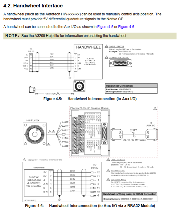
Auxiliary encoder channel: RS-422 differential; Can be used for electronic handwheel, master-slave following, and dual closed loop; Not supporting MXU analog encoder; Can be configured as encoder signal frequency division output.
PSO single axis position synchronization output: reuse auxiliary marker ± pin; Hardware triggered, maximum tracking rate of 16.6MHz, delay of 160ns; ⚠️ Mutually exclusive with MXU; The output is RS-422 differential, and external optocoupler isolation is required for long distances.
IO resources: 4 regular DI, 4 regular DO; 2 high-speed differential inputs (50ns, event capture); 1 differential analog input; 1 analog output.
IO wiring mode: digital IO supports source sourcing/sink signaling, and the same group must be unified; Inductive loads (relays) must be connected in parallel with freewheeling diodes.
2.7 TB103 Brake Power Terminal
Provide power to the onboard solid-state brake relay (24VDC maximum 2.5A); There are two wiring schemes for the brake: ① Connect the brake to the J103 feedback cable inside; ② Directly connect to TB103; Both onboard solid-state relays and IO board mechanical relays cannot be used simultaneously.
2.8 TB104 external discharge resistor (EXTSHUNT option)
Provide a calculation formula to calculate the regenerative energy based on the moment of inertia/linear mass, and select an external discharge resistor; Automatically connect and release when the bus voltage reaches about 380VDC; Resistors with high temperature and high voltage must be protected by a casing.
IO Expansion Option Board
Add terminals TB201~TB206 after installing IO
TB201 analog IO: 1-channel differential 12 bit analog input; 1-channel 16 bit analog output ± 10V.
TB202/TB203 Opto Out: 16 isolated digital outputs, maximum 60mA per channel; supports source/fill mode.
TB204/TB205 Opto In: 16 isolated digital inputs 5-24V; built-in+5V/0.5A user power output.
TB206 mechanical relay: dedicated mechanical relay for holding brake, maximum 1A; modify the switching logic of holding brake through JP1 jumper on the board; Do not use the TB103 solid-state brake on the motherboard anymore when using IO board relays.
Important: The motherboard comes with either a solid-state brake relay or an IO board mechanical relay, which cannot be activated simultaneously.
Accessories
Complete set of supporting cable part numbers;
Wiring diagram of joystick/electronic handwheel: can be connected to J104 auxiliary IO or IO expansion board; Support single axis and dual axis control levers; The handwheel can be connected in conjunction with the BBA32 module.
Maintenance chapter
Definition of LED indicator lights: PWR power supply, EN enable, FAULT fault, MARK encoder zero mark;
Control board jumper and fuse part number; Backup battery specifications;
Preventive maintenance: Regularly clean the cooling air duct and tighten the connector; Check the grounding of cable shielding.