Aerotech Ndrive HP10/20/30 PWM Digital Servo Drive
Product Overview
1.1 Model and Power Parameters
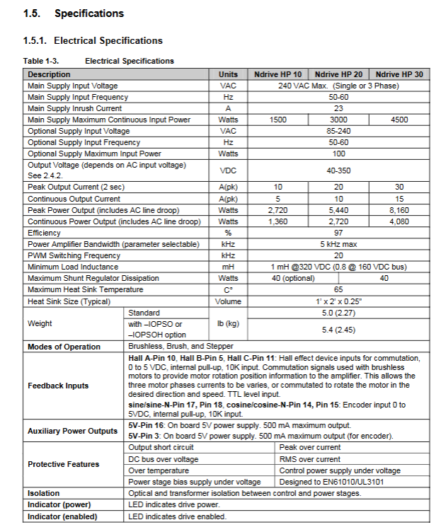
Model Peak Output Current Continuous Output Current Continuous Output Power
Ndrive HP10B 10A 5A 1360W
Ndrive HP20B 20A 10A 2720W
Ndrive HP30B‑S 30A 15A 4080W
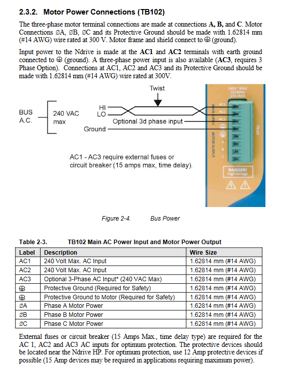
Main power supply: single-phase/three-phase maximum 240VAC, DC bus 100-320VDC; Paired with the AUXPWR option, it can achieve a 40-80VDC low-voltage bus.
PWM switching frequency 20kHz; The servo loop bandwidth software can select up to 5kHz; The overall efficiency is 97%.
Supported motor types: brushed DC, brushless AC, stepper motor.
1.2 Core Hardware Features
Main control: Harvard architecture high-speed DSP; Servo closed-loop update 1-20kHz optional.
Feedback system: supports differential TTL line driven encoders and analog sine encoders; The MXH option encoder has a maximum multiplier of 2048; Supports Hall and rotary transformers (RDP options).
Communication: 3-channel FireWire (IEEE-1394) networking; RS-232/422 debugging; ENET option adds 10/100M Ethernet.
IO basic configuration: 6 optocoupler digital inputs (including 2 high-speed inputs), 4 optocoupler outputs; 1 differential analog input, 1 analog output; Onboard 5V/500mA encoder power supply (self recovering fuse protection).
PSO position synchronization output (laser triggered): standard single axis; DUALPSO dual axis, TRIPLEPSO three-axis PSO; Single axis delay of 200ns, multi axis delay of 275ns, hardware FIFO queue, used for laser processing synchronization triggering.
Complete hardware protection: Control power undervoltage, continuous overcurrent, power level undervoltage, output phase/ground short circuit, DC bus overvoltage, IGBT overheating.
Environmental conditions: working temperature 5-40 ℃, storage -20-70 ℃; The maximum humidity for non condensing is 80% RH; for indoor use, the highest altitude is 2000m.
1.3 Main ordering options
Function Description of Options
IOPSO/IOPSOH expansion IO board, adding more isolated IO, brake relay, SSI Net, PSO optical isolation output; IOPSOH has a higher output current
DUALPSO/TRIPLEPSO dual axis/three-axis PSO laser triggered
MXH analog sine encoder multiplier board, maximum x 2048
ENET Ethernet interface, compatible with third-party network IO
RDP Rotary Transformer Feedback Interface
AUXPWR assists in maintaining power supply; Main power outage maintains control logic power supply (Keep Alive) to achieve continuous communication and feedback in emergency stop state
– S built-in discharge resistor; HP30 standard, HP10/20 optional
3P three-phase AC input
1.4 Physical dimensions
With IOPSO board: width 99mm, height 232.4mm; without IO board: width 79.4mm;
Weight: standard 2.27 kg; additional IO board 2.45 kg;
Installation: M4 screws; Reserve 1 inch of ventilation space around the equipment.
1.5 CE Compliance Declaration
The drive meets EMC&safety standards such as EN61800-3 and EN61010-1; When in use, motor cables must be shielded, power filters and magnetic ferrite rings must be added, and they must be installed inside the cabinet; Dangerous voltage still exists inside after 5 seconds of high-voltage power outage; The user is responsible for external emergency stop, grounding, and short circuit protection.
Installation and wiring configuration
Important safety warning: Cut off all power before wiring; The motor is disconnected from the mechanical load to prevent accidental rotation and injury; Not following the manual will weaken the protective ability of the equipment.
2.1 Key points for wiring grounding and EMI suppression
The 20kHz PWM driver will generate electromagnetic interference, and wiring requirements are mandatory:
The motor cable must be shielded, and the shielding layer should be grounded for protection; The motor casing is reliably grounded.
Power cables, encoders, and IO signal lines are physically separated and routed.
Install EMI power filter on the AC input end; Install specified types of ferrite beads on motors and FireWire cables.
Eliminating 50/60Hz power frequency coupling interference can increase the isolation transformer.
2.2 Power terminals
TB102 main power terminal: AC1/AC2 single-phase, AC3 three-phase input (3P option); A/B/C motor power output; Suggest 14AWG cable; The maximum external delay fuse is 15A.
TB101 (AUXPWR option) auxiliary control power supply: independent 85-240VAC input; Maintain logical power supply when the main motor bus is powered off, for emergency stop keep alive scenarios.
Can be connected to an external TV series transformer to achieve a 40/80/160VDC DC bus.
2.3 Motor wiring and phase setting
The manual provides complete wiring diagrams, cable color codes, and phase calibration processes for brushed DC (torque mode/speedometer speed mode), brushless servo, and stepper motors
Brushed DC motor:
Torque mode: directly connected to A/C; B terminal is vacant;
Speedometer mode: The speed signal is connected to J205 analog input 0, and the input voltage cannot exceed ± 10V;
Phase judgment: Forward command, with the motor flange facing itself, clockwise rotation of the shaft is in the positive direction, and reverse direction, switch the A/C.
Brushless motor: motor three-phase A/B/C, Hall HA/HB/HC connected to J207;
Aerotech’s original motor uses matching cables directly without the need for phase modulation; Third party motors require phase modulation.
There are two methods for phase modulation: ① Run the A3200 example program MsetDebug. Pm software for phase modulation; ② Cut off the power and use an oscilloscope to measure the back electromotive force and Hall timing.
The Hall signal can monitor the level status in real-time on the Nstat software diagnostic interface.
Stepper motor: two-phase stepper connected to A/B/C terminals; Swap A/B phase due to incorrect direction.
2.4 Encoder, limit, and zero return wiring
J207 main feedback channel (25 pin D-SUB): main encoder, Hall sensor, thermistor, positive and negative limit (CW/CCW), home reset, motor brake output.
J205 auxiliary encoder channel (26 pin D-SUB): The second encoder is used for master-slave following, handwheel, and multi axis PSO.
Limit switch: supports normally open/normally closed; Limit status can be viewed in Nstat software; Reverse the limit connection and directly switch the CW/CCW pins.
2.5 Multi Drive FireWire Bus Networking
Each driver S2 is assigned a unique device number (1-32) for dialing, corresponding to the A3200 axis number;
Bus topology: Recommended star daisy chain hybrid; Up to 16 drives per chain; The maximum total number of axes in the system is 32;
The cable uses NConnect series FireWire cables; Before powering on, a single driver should be tested independently and then connected to the bus to avoid the spread of faults.
2.6 ESTOP Emergency Stop Input (TB201)
TB201 is an emergency stop detection input, not the emergency stop relay itself; Users need to connect an external safety emergency stop relay circuit.
Input 5-24V; after triggering, the driver cuts off the motor power, and the AUXPWR option retains the logic power supply; It is necessary to enable ESTOP fault in the axis parameter FaultMask.
Hardware interface technology details
3.1 J205 (Auxiliary I/O, 26 pin D-SUB)
Including: second bidirectional RS-422 encoder channel; 4-channel universal output (Out8-11, Out11 can output low-speed PSO, only 1kHz); 6-way universal input In8-11, 2-channel high-speed differential input In12-13 (50ns delay, used for external event capture); 1 differential analog input ± 10V; 1 analog output ± 10V; onboard+5V power supply.
High speed input is suitable for external triggering; Ordinary input of 5-24V, if the voltage exceeds the limit, a current limiting resistor must be connected in series.
3.2 PSO Position Synchronization Output Core Principle
PSO is fully implemented in hardware and does not rely on CPU. It is used for laser marking and vector trajectory synchronization triggering
Signal source: main encoder, auxiliary encoder SSI‑Net;
The maximum single axis tracking rate is 20 MHz; Dual/three-axis 5MHz;
Hardware built-in multi-level FIFO queue (255 depth), supporting vector distance triggering and window triggering; Support data capture (collection location/IO), data update (synchronous modification of IO/analog output);
Output mode: RS-422 differential, optocoupler isolated output, open collector.
3.3 J207 motor feedback 25 pin D-SUB
Main encoder sine cosine/TTL signal; HA/HB/HC Hall; Motor thermistor; CW/CCW limit, Home returns to zero; Motor brake relay output.
Thermistor PTC: When the temperature rises and the resistance is greater than 1k Ω, the motor will overheat.
3.4 J206 RS-232/422 debugging port
Local debugging, parameter reading and writing, not used for normal motion control; The FireWire bus is prioritized for normal system operation.
Expansion Options Chapter
IOPSO/IOPSOH expansion board
TB301: Brake relay, two 16 bit analog outputs;
TB302: Two 16 bit analog inputs;
TB304/TB305: 8-way isolated output, 8-way isolated input, supporting current injection/pulling mode;
J301: PSO laser output, absolute RS-485 encoder;
J302/J303: Two SSI Net channels, used for high-speed encoder signal forwarding between multiple drivers, supporting multi axis PSO.
DUALPSO/TRIPLEPSO: To achieve 2-3 axis vector PSO triggering, it must be paired with an IOPSO board.
ENET Ethernet J204:10/100Base-T, compatible with third-party network IO, cannot replace FireWire for motion control.
RDP rotary transformer option: rotary transformer as position feedback; The manual provides hardware jumpers, software configuration, and steps for rotary zero adjustment.
Accessories
Various supporting cables: motor cables, feedback cables, FireWire bus cables;
Support connecting the joystick and handwheel (electronic handwheel) to the J205 auxiliary IO port for manual jog debugging; Provide a wiring schematic diagram.
Fault diagnosis and maintenance
Fault table: List phenomena, causes, and solutions such as overcurrent, overvoltage, overheating, and communication faults.
Control board, power board test points, and jumper configuration instructions.
Definition of LED status indicator light, quickly determine the operation, enable, and fault status of the driver.
JTAG debugging interface; Fuse and backup battery replacement part number;
Preventive maintenance: Regularly clean dust and check connector fastening.
Supporting software tools
Nstat: diagnostic tool to view real-time status of Hall, encoder, limit, and IO;
Nparm: Axis parameter configuration;
Nview HMI: Human Machine Interface;
MsetDebug. Pcm Example Program: Motor Phase Debugging Tool.