Omron NA Series Programmable Terminal Device Connection Instructions
The official manual (V119) for the connection of programmable terminal devices in the Omron NA series (NA5-7/9/12/15 inch, NA-RTDD) is aimed at electrical and automation engineers. It provides a complete list of supported devices and two connection methods, Ethernet/serial port. It provides detailed guidance on the wiring, parameter configuration, variable mapping, and communication settings of NJ/NX/NY, CS/CJ/CP, NX safety controllers, and multi axis controllers. It includes the production of serial port cables, the use of CJ1W-CIF11 conversion modules, and clarifies safety specifications, EMC protection, and data security requirements. It is the core basis for the network debugging of the NA series HMI and Omron full series controllers.
Supporting devices (core)
The NA series can be connected to Omron’s entire range of controllers, with the following communication methods:
Controller series communication mode driver
NJ/NX/NY Ethernet/CIP
CS/CJ/CP Ethernet, Serial FINS/EtherNet/IP/Host Link
NX Security Controller Ethernet
CK3E/CK3M Multi Axis Ethernet Modbus/TCP
Two connection methods
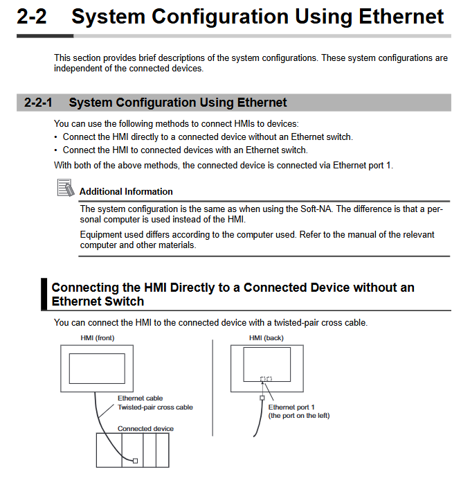
1. Ethernet connection (mainstream)
Topology: direct connection (crossover), switch (straight through)
Requirement: IEEE802.3i/u/ab, shielded Ethernet cable, single ended grounding
Recommended Switch: Omron W4S1 Series (Supports QoS)
Settings: IP address, subnet mask, gateway, timeout (default 2s)
2. Serial port connection (compatible)
Standard: RS-232C, RS-422A
Parameters: 7 data bits, even parity check, 2 stop bits (7/E/2)
Baud rate: 9600/19200/115200 bps
Distance: RS-232 ≤ 30m, RS-422 ≤ 50m (via CJ1W-CIF11)
Device Connection Configuration (Core Steps)
1. NJ/NX/NY series (Ethernet)
Controller: Set the built-in EtherNet/IP port IP
HMI: Sysmac Studio Configure Ethernet Parameters
Device registration: automatic recognition of internal devices, manual addition of external devices
Variable import: Supports importing BOOL/INT/REAL/STRING directly from the controller
2. CS/CJ/CP series (three methods)
FINS Ethernet: Set node number, network number, and frame length to 2000 bytes
EtherNet/IP: Tag Variables, CIP Communication
Host Link serial port: RS-232/422, CX Programmer configuration port
3. NX Security Controller (Ethernet)
Only supports built-in EtherNet/IP ports
Variables: Supports structures, arrays, and enumerations
Safety precautions: Cannot be used for safety related stop functions
4. Multi axis controller CK3E/CK3M (Modbus/TCP)
Enable: Sys.ModbusServerEnable=1
Data: All processed as 32-bit floats
Address area: I/M/P/Q area
Appendix: Cables and Accessories
1. Production of serial port cables
RS-232C: 9-pin D-SUB, SD ↔ RD、RS ↔ CS and SG share the same land
RS-422A: Differential signal, RDA ±, RDB ±, SDA ±, SDB ±
Shielding: Single ended grounding to avoid ground loops
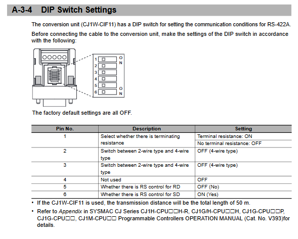
2. CJ1W-CIF11 conversion module
Function: RS-232C ↔ RS‑422A
Power supply: HMI serial port * *+5V/40mA**
DIP settings:
SW1: Terminal resistor (ON)
SW2/SW3: 4-line mode (OFF)
SW6: SD control (ON)
Size: 18.2 × 34.0 × 38.8mm, weight 20g
Safety and Standards
1. Safety Warning
Strictly prohibited for use in emergency stop, safety door and other safety circuits
Do not disassemble or touch the terminals when powered on
Lithium batteries must not be short circuited, disassembled, or burned
2. Proper use
Installation panel thickness: 1.6~6.0mm
Fixed torque: 0.5~0.6N · m
Environment: 0~55 ℃, no condensation, no corrosive gas
3. Network security
Install antivirus software, strong passwords, and regular updates
Firewall closes useless ports, VPN remote access
Use USB/SD card with caution to prevent data tampering
Key issues
Question 1 (Connection Selection)
What are the connection methods between NA series HMI and CJ series PLC? What are the applicable scenarios and limitations for each? answer:
FINS Ethernet: Fast speed, long distance, suitable for fixed cabinet networking, requires IP and node number configuration.
EtherNet/IP: Supports tag variables without address mapping, suitable for new systems.
Host Link serial port: simple wiring, average anti-interference, suitable for retrofitting old equipment, distance ≤ 50m.
Question 2 (Serial Communication)
What are the standard settings and wiring points for DIP switches when using CJ1W-CIF11 to convert RS-232 to RS-422? answer:
DIP settings: SW1=ON, SW2=OFF, SW3=OFF, SW5=OFF, SW6=ON
Wiring: RDA -/RDB+, SDA -/SDB+strictly twisted pair, shielding layer single ended grounding.
Power supply:+5V is provided by the HMI serial port 6-pin, with a maximum transmission of 50m.
Question 3 (Variables and Data)
What are the core differences in variable mapping between NA series HMI and NJ/NX controllers, and CS/CJ controllers? answer:
NJ/NX: Directly import global variables, support structures, arrays, enumerations, time types, and automatic matching.
CS/CJ: Must be mapped according to CIO/HR/AR/DM/T/C address, only supports basic types, and requires manual address specification.