OMRON SYSDRIVE 3G3KV-EV2 series frequency converter
Product basic positioning
Product model: 3G3KV — EV2 (European version)
Voltage level: 200V single-phase/three-phase, 400V three-phase
Suitable motor: 0.1~3.7kW
Control mode: sine wave PWM
Frequency range: 0.1~400Hz
Overload capacity: 150%/1min
Hardware Structure and Installation
core component
Digital Operator (3G3KV-PJOP110)
Main circuit terminal, control circuit terminal
CHARGE indicator light (must be turned off after power failure before operation)
Installation requirements
Installation method: Vertical installation
Heat dissipation spacing: left and right ≥ 30mm, up and down ≥ 100mm
Environmental temperature: -10~40 ℃ (with top cover); -10-45 ℃ (without top cover)
Environmental conditions: dustproof, moisture-proof, corrosion-resistant, and vibration resistant
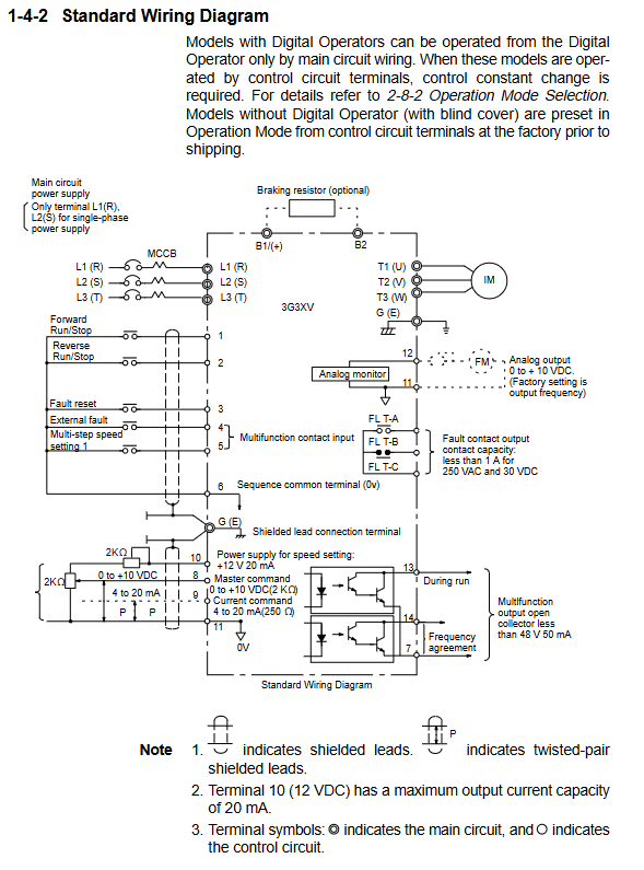
Wiring specifications
Main circuit terminal
Terminal function
L1 (R)/L2 (S)/L3 (T) power input
T1 (U)/T2 (V)/T3 (W) motor output
B1 (+)/B2 braking resistor
G (E) grounding (≤ 100 Ω)
Control circuit terminal
Switching quantity: forward/reverse rotation, fault reset, external fault, multi-stage speed
Analog quantity: 0~10V/4~20mA frequency given
Output: Running signal, frequency arrival, fault relay (FLT-A/B/C)
Wiring protection
MCCB circuit breaker on the input side
Long distance wiring reduces carrier frequency (5kHz for ≤ 100m)
Separate control cables from power lines and use shielded wires
Digital operator and parameter setting
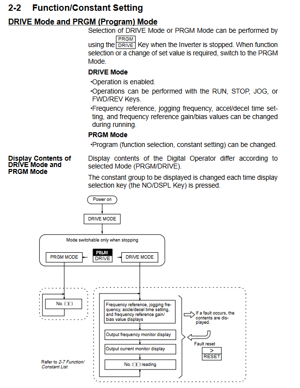
Operation Mode
DRIVE mode: operation, start stop, jog, frequency setting
PRGM mode: parameter modification, function configuration
Core parameter group
Parameter Category Key Parameters Factory Value
Operation mode 01 (operation mode selection) 0011
V/f characteristic 02 (maximum frequency) 60.0Hz
Acceleration and deceleration 09/10 (acceleration and deceleration time 1) 10.0s
Motor protection 19 (rated current of motor) by model
Carrier frequency 40 4 (10kHz)
Common Functions
4-speed (parameters 13-16)
Jogging operation (parameter 17, default 6.0Hz)
DC braking (start/stop braking)
Stall prevention (acceleration/operation/deceleration)
Slip compensation (steady speed)
Protection function
Fault protection (shutdown)
OC: Overcurrent (approximately 200% of rated current)
OV: Overvoltage (200V level>410V; 400V level>820V)
UV: Under voltage
GF: Grounding fault
OH: Overheating of heat sink
OL1: Motor overload
OL2: Inverter overload
Warning protection (non-stop)
OL3: Over torque warning
Stall prevention (current limitation)
External fault (EF4/EF5)
Troubleshooting and Maintenance
Common fault handling
Possible causes and solutions for fault display
OC accelerates too quickly, output short circuit extends acceleration and deceleration, check wiring
OV decelerates too quickly, regenerative load prolongs deceleration time, and braking resistor is added
OL1 motor overload reduces load and adjusts protection current
Poor heat dissipation of OH, cleaning fan, improving ventilation
regular maintenance
Check the terminal fastening and clean the heat sink
Replace the cooling fan and check the capacitor
Insulation test (500V megohmmeter, ≥ 1M Ω)
Disassembly and assembly of operator
The power must be cut off and the CHARGE light must be turned off before operation
Key issues
What are the two operation control modes of 3G3KV frequency converter? How to switch? There are two methods: digital operator control and external terminal control. Switching method: Modify parameter 01, set it to 0000 to enable external terminal control, and set it to 0011 to enable operator control.
What are the absolutely prohibited operations for the main circuit wiring?
It is strictly prohibited to connect the power input to the T1/T2/T3 output terminals
It is strictly prohibited to connect power factor compensation capacitors at the output end
Do not touch the main circuit terminals when powered on (wait for the CHARGE light to turn off)
It is strictly prohibited to short-circuit or directly switch the contactor on the output side
How to set the motor protection function? What should I pay attention to?
Setting steps:
Parameter 18: Activate the electronic thermal relay (default is 0000)
Parameter 19: Input the rated current of the motor (according to the motor nameplate)
Attention: One to multiple motors require an external thermal relay, and the carrier frequency should be reduced during low-speed operation.