OMRON C200H Series PLC (CPU01-E/03-E/11-E) Operating Instructions
Scope of application and safety regulations
Compatible Models
C200H CPU01‑E / 03‑E / 11‑E
Supporting I/O units, special function units, and linking units
Mandatory safety requirements
It is necessary to disconnect the power and disassemble the unit, connect the wiring, and set the DIP switch
Grounding resistance * * ≤ 100 Ω * * to prevent electric shock and interference
Emergency stop, interlock, and limit circuits must be configured externally
Output relay burnout/transistor breakdown may cause abnormal output, requiring external safety measures
Anti static: Release static electricity before contacting the unit
runtime environment
Temperature: 0~50 ℃, humidity: 20~90% RH, no condensation
Prohibited: direct sunlight, dust, corrosive gases, strong vibration, strong electromagnetic
Hardware structure and indicator lights
1. Definition of CPU indicator light
Meaning of indicator light status
POWER is constantly on and the power supply is normal
RUN is constantly on and running normally
ALARM flashing non fatal abnormality (low battery, cycle timeout)
ERROR is constantly on, indicating a fatal error. Stop running and output fully off
OUT INHIBIT constant light output disabled (SR25215=ON)
2. System architecture
Composed of CPU rack and up to 2 expansion I/O racks
Bottom plate: 3 slots, 5 slots, 8 slots
I/O allocates addresses by slot, with each slot occupying 1 IR word (16 dots)
Core memory area (mandatory)
All regions are managed by word (16 bit), with some supporting bit addressing.
Regional abbreviation address range, power failure maintenance purpose
Internal relay IR 000~235 No I/O point, internal coil
Special relay SR 236~255, partial system flags, clocks, errors
Auxiliary relay AR 00~27 is a dedicated symbol, error history, and clock
Data storage DM 0000~1999 refers to data storage and indirect addressing
Keep relay HR 00~99 in a power-off state
Timer/Counter TC 000~511 SV keeps timing and counting
Link relay LR 00~63 No PLC link data
Temporary relay TR 00~07, ladder diagram branch temporary storage
Key System Position (SR)
SR25315: First cycle flag (ON in the first cycle of startup)
SR25313: Constant ON; SR25314: Constant OFF
SR25212: I/O Status Hold Bit
SR25215: Output fully closed position
SR25503: Instruction execution error flag ER
Fundamentals of Programming
1. Programming method
Shape: Ladder Diagram
Text: Mnemonic mnemonic (directly input by programmer)
Tools: Handheld programmer, GPC, FIT, LSS software
2. Standard process
I/O allocation and address planning
Draw a ladder diagram
Convert to mnemonic symbol
Programmer writes into PLC
Grammar check → Run debugging → Optimize → Backup
3. Rules must be followed
END (01) must be added at the end of the program, otherwise it will not be executed
An output bit can only be driven in one OUT/SET/KEEP
TC numbers 000-511 can only be defined once (cannot be repeated)
Core instruction classification
1. Basic logic instructions
LD/LD NOT: Load normally open/normally closed
AND/AND NOT: series connection
OR/OR NOT: Parallel connection
AND LD/OR LD: Block Series/Block Parallel
OUT/OUT NOT: Output
DIFU (13)/DIFD (14): rising edge/falling edge (single cycle ON)
KEEP (11): Latch (Set/Reset)
2. Process control
IL (02)/ILC (03): Interlock, segment reset when conditions are not met
JMP (04)/JME (05): Jump, skip program without changing state
STEP/SNXT: Step Control (Sequential Process)
SBS/SBN/RET: Subroutine calls
3. Timing and Counting
TIM: 0.1s timer, set value 0~999.9s
TIMH (15): High speed timer
CNT: Down Counter
CNTR (12): reversible counter
4. Data processing
MOV/MVN: Transfer/Reverse Transfer
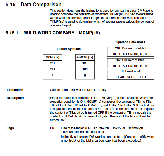
CMP: Comparison
ADD/SUB/MUL/DIV: BCD operation
ADB/SBB: Binary Operations
SFT/SFTR: Shift Register
Program Execution and Timing
1. Scanning mechanism
Input refresh → Program execution → Output refresh loop execution
The program executes from top to bottom according to the address
The input only refreshes at the beginning of the cycle, and the output only refreshes at the end of the cycle
2. Key timing indicators
Basic instruction execution: 0.4 μ s level
Scanning cycle: can be viewed on the programmer
SR25309 cycle error triggered over 100ms
Operation and Debugging (Programmer)
1. Core operations
Mode switching: Program, Monitor, RUN
Memory clearing: clearing programs, I/O, DM, HR, etc
I/O table registration: Match actual units, verify abnormal alarms
Program check: Level 3 syntax check, detecting circuit errors, duplicate outputs, etc
2. Monitoring function
Monitoring bit ON/OFF status
Timer/counter current value PV
Real time display of scanning time
Forced reset/reset position
3. Fault handling
Look at ERROR/ALARM lights
Read error codes and AR/SR error flags
Common reasons: program without END, mismatched I/O configuration, low battery, overload, short circuit
Key issues
Question 1: Which of the 8 memory regions of C200H can maintain data after power failure? What are their respective purposes?
Answer: The areas for power outage maintenance are AR, DM, HR, TC (SV).
HR: Save switch status, alarm, manual/automatic mode, and other states.
DM: Save parameters, formulas, cumulative values, error history, and support indirect addressing.
AR: Save system errors, communication status, clock, and number of power outages.
TC: The timer/counter set value SV is maintained, and the current value PV is not maintained.
Do not maintain: IR, SR, LR, TR, reset to zero after restart.
Question 2: IL/ILC and JMP/JME both skip program segments. What is the core difference between the two?
answer
IL (02)/IL (03) interlock: When the condition is OFF, OUT reset, TIM reset, CNT hold, KEEP hold within the section are used for safe disconnection.
JMP (04)/JME (05) Jump: When the condition is OFF, it completely skips and does not execute, and all output/timer/counter states are fully maintained for cycle optimization and selective execution.
Simple note: IL is “cut off reset”, JMP is “skip not move”.
Question 3: What are the three most common errors that cause C200H programs to not run or output abnormally? How to avoid it?
answer
Missing END (01) → The program does not execute at all; END must be added in the last line.
An output bit is driven multiple times by OUT → only the last one takes effect, and the previous logic fails; Only one OUT/SET/KEEP is allowed for one output.
TC number duplicate definition → Timer/counter malfunction; Each TC000~511 can only use TIM/TIMH/CNT/CNTR once.