OMRON 3G3MV Multi functional Compact Inverter
The installation and setup manual for Omron SYSDRIVE 3G3MV series multifunctional compact frequency converter covers 0.1~7.5kW, 200V single-phase/three-phase, 400V three-phase models, providing detailed instructions on safety specifications, installation dimensions, main/control circuit wiring, digital operator operation, parameter replication and verification, complete parameter list, protection diagnosis and maintenance. It supports V/f and sensorless vector control, PID closed-loop, multi-stage speed, protocol communication, and comprehensive protection against overcurrent/overvoltage/overload/grounding. It provides practical functions such as parameter copying, fault logs, and fan automatic control, and is suitable for speed regulation of small fans, water pumps, conveyors, machine tools and other equipment.
Safety regulations (mandatory requirement)
1. Security level
DANGER: Avoid death/serious injury, do not open the cover, do not operate with electricity
Warning: To avoid injury or death, the power must be turned off and the indicator light must be turned off before operation
CAUTION: Avoid minor injuries/equipment damage, prohibit exposure to sunlight, corrosion, and dusty environments
2. Core security rules
After power failure, wait for at least 1 minute until the CHARGE light goes out before operating
Grounding requirements: 200V level ≤ 100 Ω, 400V level ≤ 10 Ω
It is strictly prohibited to connect the power supply to the U/V/W output terminal
An external emergency stop circuit must be configured, and the STOP button on the panel is not a safety guarantee
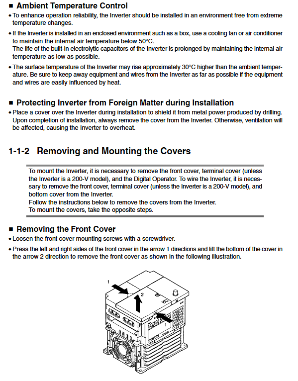
Installation specifications
1. Environment and size
Working temperature: -10~50 ℃ (low power); -10~40℃(5.5~7.5kW)
Humidity: ≤ 95% RH, no condensation
Installation direction: Vertical upward
Heat dissipation spacing: left and right ≥ 30mm, up and down ≥ 100mm
2. Model size (representative)
Power width (mm) Weight (kg)
0.1~0.75kW 76~128 0.6~1.1
1.5~3.7kW 131~143 1.4~2.1
5.5~7.5kW 170 4.6~4.8
Wiring specifications
1. Main circuit terminal
Terminal function
R/L1, S/L2, T/L3 three-phase power input
U/T1, V/T2, W/T3 motor outputs
B1 and B2 braking resistors
+1. +2 DC bus
PE grounding
2. Control circuit terminals
S1~S7: Multi functional inputs (forward rotation, reverse rotation, fault reset, multi-stage speed, etc.)
FR, FC: 0~10V/4~20mA frequency given
MA/MB/MC: Fault relay output
R+/R -, S+/S -: RS-422/485 communication
3. Dial switch
SW1: Select input type NPN (default)/PNP
SW2:
Pin1: RS-422/485 terminal resistor ON/OFF
Pin2: Frequency Given Voltage (OFF)/Current (ON)
Digital operator (panel)
1. Display mode
FREF: Frequency Setting
FOUT: Output frequency
IOUT: Output current
MNTR: Multi functional monitoring (voltage, torque, fault log)
PRGM: Parameter Settings
2. Core functions
Parameter copying: n176 select rEd (read) → CPy (write) → vFy (verify)
Parameter Protection: n001 Set Write Protection/Initialization
Fault query: U-09 View the last 4 faults
Core Parameters (Key Tables)
1. Basic operating parameters
Default parameter name setting range
N001 parameter protection/initialization 0~11 1
N002 control mode 0=V/f, 1=vector 0
N003 run command selection 0~3 0
N004 frequency command selection 0~9 0
N036 motor rated current 0.0~150% model setting
2. Motor protection parameters
Parameter name setting
N037 motor protection type 0=ordinary motor, 1=dedicated motor, 2=unprotected
N038 protection time 1-60min, default 8min
3. Multi functional input (n050~n056)
Can be set: forward rotation, reverse rotation, fault reset, multi-stage speed, jog, emergency stop, PID control, etc.
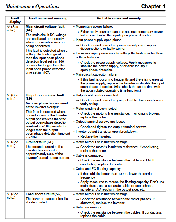
Protection and fault diagnosis
1. Fatal malfunction (shutdown)
Reason for code malfunction
OC overcurrent output short circuit, rapid acceleration
OV overvoltage deceleration too fast, regenerative energy
UV undervoltage power outage, phase loss, loose wiring
OH overheating, poor heat dissipation, fan failure
OL1 motor overload load, incorrect current setting
OL2 frequency converter overload, insufficient capacity
GF grounding fault motor/cable leakage
SC output short circuit, phase to phase short circuit
2. Warning (without stopping the machine)
UV, OV, OH, OL3, CAL (communication standby), OP (parameter error)
Maintenance and upkeep
Regular inspection: terminal fastening, cleaning of heat sink, fan operation
Fan replacement: snap on disassembly, pay attention to wind direction
Fault reset:
Panel STOP/RESET button
Multi functional terminal reset
Power off and restart
Insulation test: It is prohibited to conduct voltage withstand tests on frequency converters to prevent damage to power devices
Key issues
Question 1: What is the difference between vector control and V/f control in G3MV? What loads are suitable for each?
answer
V/f control (n002=0): Universal type, suitable for parallel connection of fans, water pumps, and multiple motors, with simple parameters and moderate low-speed torque.
Sensorless vector control (n002=1): high-precision type, suitable for conveyor belts, presses, single motors, with high low-speed torque and high speed accuracy.
Selection rules: For single motor high torque, choose vector, and for multi motor/fan/water pump, choose V/f.
Question 2: How to correctly set the motor overload protection OL1? What are the consequences of setting errors?
answer
Setting steps:
N036 input motor nameplate rated current
N037 Select motor type (0 normal/1 dedicated)
N038 sets protection time (default 8 minutes)
Consequences of Error:
Low current setting → frequent false alarms
Current set too high → motor burnt out without protection
Multiple motors must be equipped with n037=2 and an external thermal relay.
Question 3: How to use the parameter copying function (n176)? Which parameters cannot be copied?
answer
Usage steps:
N001 is set to 4 (allowing all modifications)
N177 is set to 1 (read allowed)
N176 Set rEd (source machine) → Change panel → CPy (write target machine) → vFy (verify)
Non copyable parameters:
n176、n177、n178、n179
Rated current of motor V/f、 Carrier frequency and other relevant parameters of the aircraft model