Yaskawa VS-616PC5/P5 series variable torque frequency converter
Product basic positioning
This document is the user manual for Yaskawa VS-616PC5/P5 variable torque frequency converter, only applicable to software versions 5110/5120 and above models.
Series: VS-616PC5 (low power), VS-616P5 (high power)
Voltage: 230V level, 460V level
Power: 0.5HP -500HP
Control mode: sine wave PWM+global automatic torque boosting
Applicable loads: Variable torque loads such as pumps, fans, conveyors, etc
Core specification parameters
Electrical and Environmental
Project parameters
Output frequency 0.1-400Hz
Frequency accuracy number: 0.01%; Simulation: 0.1%
Overload capacity VT: 120%/1min; CT:150%/1min
Carrier frequency 2.5-15kHz (n054 setting)
Environmental temperature -10-+40 ℃ (NEMA1); -10-+45 ℃ (open shelf)
Protection level IP20 (NEMA1), IP00 (open rack)
Model differentiation
PC5:0.5–25HP, Compact book style
P5:30–500HP, High power models
Torque mode: n116=1 (VT variable torque), n116=0 (CT constant torque)
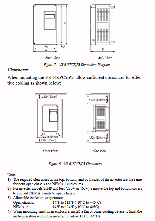
Installation specifications
Installation direction: It must be installed vertically to ensure smooth cooling air ducts
Distance requirement: Up and down * * ≥ 120mm * *, left and right * * ≥ 50mm**
Environmental taboos: dustproof, moisture-proof, corrosion-resistant, no direct sunlight
Disassembly and assembly of the operator: Disassemble after power off, and do not plug or unplug with power on
Wiring instructions
1. Main circuit terminal
Terminal function
L1/L2/L3 three-phase power input
T1/T2/T3 frequency converter output connected to motor
B1/B2 brake resistor connection
G (E) Grounding (230V: ≤ 100 Ω; 460V: ≤ 10 Ω)
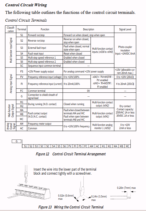
2. Control circuit terminals
Terminal function
S1 running forward
S2 reverse operation
S3-S6 multifunctional input (fault, reset, multi-stage speed, etc.)
FV/FI analog quantity given (0-10V/4-20mA)
MA/MB/MC fault relay output
M1/M2 multifunctional output
3. Wiring taboos
It is strictly prohibited to connect the power supply to the T1/T2/T3 output terminals
Motor line length * * ≤ 100m * *, carrier frequency needs to be reduced for long distances
Separate strong and weak electrical wiring, use shielded wires for control lines
Operation mode
Two control modes
Local: Directly controlled by JVOP-130P panel for start stop and speed regulation
Remote: Controlled by control terminals or MODBUS communication
Switch: Panel LOCAL/REMOTE key, parameter n002 setting
Basic operating procedures
Power on inspection shows normal operation
Select operation mode
Set the rated current of the motor (n033)
Set acceleration and deceleration time (n018/n019)
Start the operation, observe the steering and current
Core parameter function (n001 – n116)
1. Basic parameters
Default values for parameter functions
N001 Password/Initialization 1
N002 operation mode selection 3 (remote terminal)
N011 maximum frequency 60.0Hz
N018 acceleration time 1 10.0s
N019 deceleration time 1 10.0s
N033 motor rated current model matching
N069 stops DC braking for 0.0 seconds
2. Advanced features
Multi speed: 4 fixed frequencies (n024-n027)
PID control: closed-loop constant voltage/constant current/constant temperature (n084 open)
Frequency hopping function: Avoid resonance points (n062-n064)
Energy saving control: light load automatic voltage reduction (n096 on)
S-curve: Smooth start stop, reduce impact (n022)
Protection function
The frequency converter has complete protection, and stops outputting and alarms when there is a fault:
OC: Overcurrent (approximately * * 200% * * rated current)
OV: Overvoltage (DC>410V/820V)
UV: Under voltage
GF: Grounding fault
OL1: Motor overload
OL2: Inverter overload
OH: Overheating of radiator
SPI: Input phase loss
Maintenance and Inspection
Regular projects: Terminal fastening, heat sink dust removal, fan inspection
Vulnerable parts: cooling fan (20000h), electrolytic capacitor
Safety requirement: After power off, wait for 5 minutes and confirm that the CHARGE light is off before operating
Fault diagnosis
View operator alarm codes
Check the load, wiring, and parameter settings
External reset or power-off restart
Enable * * Automatic retry (n060) * * to automatically restore short-term faults
Key issues
Question 1: What is the core difference between VS-616PC5 and P5? How to choose between VT and CT modes?
answer:
PC5 is a compact low-power model ranging from 0.5 to 25HP; P5 is a high-power model with a capacity of 30-500HP.
VT (Variable Torque): n116=1, suitable for fans and water pumps, overload 120%/1min.
CT (constant torque): n116=0, suitable for conveyor belts and compressors, overload 150%/1min.
Question 2: How can the frequency converter achieve local/remote control switching? What are the core parameters?
answer:
Panel operation: Press the LOCAL/REMOTE key to switch between shutdown states.
Parameter settings: n002 selects the control source, 3 is remote terminal, 0 is local panel.
The switching logic is determined by n111 whether to accept existing external operating signals.
Question 3: What problems can be caused by excessively long motor wires? How to handle?
answer:
Motor wires exceeding 100m will generate leakage current, causing OC/GF faults and damaging motor insulation.
Solution: Reduce the carrier frequency (n054) and set it below 5kHz for long distances; Install output reactors if necessary.