OMRON ZFV series intelligent visual sensor
Product Overview and Safety Standards
Product positioning
Ultra high speed CCD intelligent visual sensor, no programming required, LCD visual operation.
Version: Ver. 2.0, added functions such as image logging, measurement data reset, and communication settings.
Safety and usage taboos
Non safety grade products cannot be used for personal safety protection.
Environment: 0~50 ℃, 35%~85% RH, no corrosion/dust/strong electromagnetic.
Power supply: DC24V ± 10%, reverse connection is prohibited, strong and weak electricity are separated and wired.
Maintenance: Use air to clean the lens, and do not use acetone/alcohol.
Hardware composition and specifications
1. Core components
Key parameters of component model
Sensor head ZFV-SR10 (narrow field of view) with a distance of 34-49mm and a field of view of 5 × 4.6~9 × 8.3mm
ZFV-SR50 (wide field of view) distance 38~194mm, field of view 10 × 9.2~50 × 46mm
Amplifier unit ZFV-A10/A15 NPN/PNP, simple type: pattern/brightness detection
ZFV‑A20/A25 NPN/PNP, Standard type: Full function testing
2. Electrical and Performance
Processing speed: high-speed 4ms/standard 8ms/high-precision 12ms
Resolution: Maximum 468 × 432
Bank quantity: 8 groups, expandable to 128 groups
Input/output: TRIG trigger, TEACH teaching, BANK switching ENABLE/ERROR/OUTPUT
Installation and wiring
Installation method
DIN rail installation (35mm), panel installation (with ZS-XPM1 bracket).
The amplifier must be installed vertically to ensure heat dissipation.
I/O wiring definition
Brown: 24V; Blue: GND; Black: OUTPUT; Orange: ENABLE; Light Blue: ERROR
Yellow: TEACH; Powder: TRIG; Gray/Green/Red: BANK1~3
Group installation
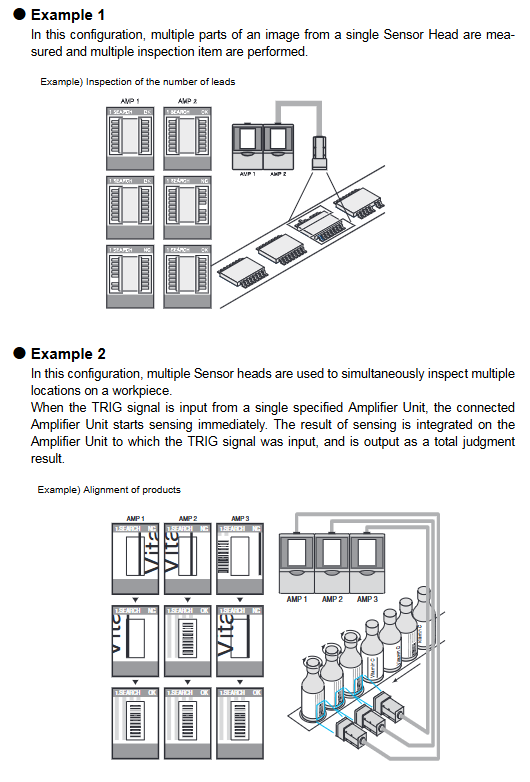
Up to 5 amplifiers can be linked together, with shared triggering and comprehensive judgment output.
The image is transmitted from right to left and triggered by the rightmost host for unified input.
Operation and Setting
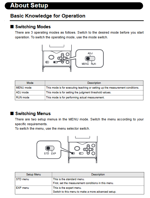
Three working modes
MENU mode: demonstration, parameters Bank、 System settings.
ADJ mode: Adjust the judgment threshold (related value/area/width, etc.).
RUN mode: Run detection, output results, support display switching.
Teaching demonstration types (8 types)
PATTERN (SEARCH/MATCH): Shape presence/matching degree
BRIGHT: Brightness/Scratches
Area: Area
WIDTH: Width
POSITION: Position
COUNT: Counting
CHARA1/CHARA2: Character Whole/Missing Character Detection
Key setting items
Measurement speed: FINE/NORMAL/HIGH SPEED
Trigger mode: TRIG synchronous/Continuation continuous
Output: OK ON/NG ON, single pulse, delay
ECO mode: Screen off after 3 minutes of inactivity (default ON)
Group linkage (Gang Mounting)
rule
Maximum connection: 5 units
Trigger/Teach/Enable: Only valid on the host
Output: Can choose between comprehensive judgment (ALL) or individual output (EACH)
data flow
Image: Right → Left
Trigger: Right → Left
Output/Enable: Left → Right
Malfunctions and anomalies
Common exceptions
No image: lens not connected, light source turned off, focusing error
Not outputting: mode not RUN, trigger not inputted, output polarity reversed
Teaching failure: workpiece out of field of view, improper area, too bright/too dark
error code
HEAD IS NOT CONNECTED: Sensor head not connected
TEACHING FAILED: Teaching failed
BANK DATA ERROR: Bank data exception
Key issues
Question 1: What is the core difference between the ZFV simplified model (A10/A15) and the standard model (A20/A25)?
answer:
Simple type (A10/A15): Only supports two types of detection: PATTERN and BRIGHT, suitable for basic presence/absence/brightness judgment.
Standard type (A20/A25): Supports all 8 types of detection (area, width, position, counting, characters, etc.), with complete functionality.
Question 2: How many groups can ZFV collaborate with at most? How to configure triggering and output during linkage?
answer:
Up to 5 amplifiers can be linked together.
The triggering, teaching, and enabling signals are only valid for the rightmost host.
The output can be set as:
ALL: All unit results are synthesized and output uniformly by the host.
EACH: Each unit outputs results separately.
Question 3: How to save ZFV parameters? What will happen if the power is not saved?
answer:
The parameters are automatically saved when switching to RUN mode or when external TEACH teaching is successful.
If the power is directly cut off after modifying the MENU/ADJ mode, all changes (including teaching) will be lost and the state before the power outage will be restored.