OMRON 3G3MX2 frequency converter
Product specifications and scope of application
Model system
200V single-phase: 3G3MX2-ABxx (0.1~2.2kW)
200V three-phase: 3G3MX2-A2xx (0.1-15kW)
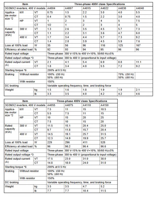
400V three-phase: 3G3MX2-A4xx (0.4-15kW)
Core electrical parameters
Project parameters
Output frequency 0.1~400Hz
Starting torque 200% @ 0.5Hz (no sensing vector)
Overload capacity CT: 150%/60s; VT:120%/60s
Carrier frequency 2-15kHz
Control mode V/F, sensorless vector, free V/F
Communication interface RS485 Modbus RTU (standard)
Safety function STO (ISO 13849-1 PLd)
Safety regulations (mandatory requirement)
High voltage hazard: Wait for 10 minutes after power failure before operation, ensure that the CHARGE light is off
Installation requirements: It must be installed on flame-retardant steel plates and vertical vibration free walls
Grounding specifications: 200V level ≤ 100 Ω, 400V level ≤ 10 Ω, single point grounding
Prohibited items: Do not connect the power supply to the output terminal U/V/W; Prohibit connecting capacitors on the output side
Personnel requirements: Only professional electrical personnel are allowed to install and debug
Installation and heat dissipation
Installation direction: Vertical installation to ensure unobstructed heat dissipation ducts
Distance requirement: Up, down, left, right * * ≥ 100mm**
Heat dissipation conditions: ambient temperature * * -10~50 ℃ * *, humidity 20~90% RH
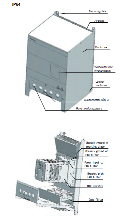
IP54 model: equipped with dust and water resistance, EMC filter, suitable for harsh environments
Wiring specifications
1. Main circuit wiring
Terminal function
R/L1, S/L2, T/L3 three-phase power input
L. N single-phase power input
U/T1, V/T2, W/T3 motor outputs
+1. P/+2 DC reactor/braking unit
RB braking resistor
FG grounding
2. Wiring specifications
Wire diameter: AWG16~AWG2 (matched by power)
Screw torque: M3.5 (1.0N · m)~M8 (8.8N · m)
Fuse: Class J, 10A~80A (matched by model)
3. Control circuit
Intelligent input: 7 channels, customizable functions (forward rotation, reverse rotation, multi-stage speed, etc.)
Intelligent output: 3 channels, relay/open collector
Analog quantity: 0~10V/4~20mA input, 0~10V output
USB:mini-B, Used for PC debugging
RJ45: Remote Operator Interface
Parameter system (core grouping)
D group (monitoring): output frequency, current, temperature, fault history, life monitoring
F group (main parameters): target frequency, acceleration and deceleration time, operating direction
Group A (standard function): frequency command source, operation command source, highest frequency, base frequency
Group B (Fine tuning): Carrier frequency, torque boost, electronic thermal relay, protection threshold
Group C (Smart Terminal): Input/Output Function Allocation
H group (motor parameters): motor pole number, rated current, self-tuning
Core functions
Speed control
16 preset speeds, binary/bit control modes
Acceleration and deceleration: linear, S-curve, U-curve, inverse U-curve, EL-S curve
PID control
Closed loop feedback, supporting temperature/pressure/flow closed-loop
Sleep function, PID reverse output, feedforward control
torque control
Torque limitation and torque bias under sensorless vector
safety function
STO safety torque shutdown, reaching PLd/Cat. 3
protection function
Overcurrent, overvoltage, undervoltage, overload, brake resistor overload, ground fault, overheating
Debugging and operation
keyboard operation
RUN/STOP/RESET: Run, Stop, Reset
PRG: Parameter Switching; ▲/▼: Numerical adjustment; SET: Confirm
Power on testing steps
Confirm wiring → Set command source=keyboard → Set motor parameters → Test run → Check steering direction
Parameter initialization: restore factory settings to avoid parameter confusion
Fault diagnosis and maintenance
Fault monitoring: D081~D086 record the last 6 faults (code, frequency, current, voltage)
Common Faults
E01: Overcurrent; E02: Overvoltage; E05: Overload; E06: Overload of braking resistor
Maintenance points
Cooling fin cleaning, fan inspection, capacitor life monitoring
Check the wiring torque every year and replace vulnerable parts every 3-5 years
Key issues
Question 1: What is the difference between the two overload levels CT/VT of MX2 frequency converter, and what scenarios are they applicable to?
Answer: CT (constant torque/heavy load): 150%/60s overload, suitable for equipment such as conveyors, cranes, elevators, etc. that require high starting torque; VT (Variable Torque/Light Load): 120%/60s overload, suitable for variable torque loads such as fans and pumps, with higher rated current at the same power.
Question 2: How to quickly set the MX2 inverter to “keyboard controlled start stop+keyboard set frequency” through the keyboard?
Answer: 1 Set A001=02 (frequency command=keyboard); 2. Set A002=02 (run command=keyboard); 3. Set A003 (base frequency), A004 (highest frequency), H004 (number of motor poles); 4. Press RUN to start, ▲/▼ adjust the frequency, and STOP to stop.
Question 3: What must be done when the output line of the MX2 inverter motor exceeds 10 meters? Why?
Answer: An output reactor/surge filter must be installed (mandatory requirement for 400V level). Because the PWM waveform can generate surge voltage on the long line, it may break through the motor insulation, causing damage to the motor and reducing interference.