Safety and installation wiring instructions for GP477R-EG11 touch human-machine interface
The safety and installation wiring manual for GP477R-EG11 touch human-machine interface specifies the core configuration of AC100V power supply, EL high brightness display screen+touch panel, standardizes safety warnings, installation dimensions, serial/print/AUX interface definitions, wiring grounding, power and signal protection. The interface includes RS-232C/RS-422 serial port, 15 pin AUX, 14 pin print port, and installation requires waterproof gaskets and 0.5-0.6N · m torque. It is strictly prohibited to disassemble/replace batteries by oneself. Touch cannot be used in life safety scenarios.
Safety Warning (Mandatory Compliance)
Electric shock and fire risk
The wiring must be disconnected, and disassembly, modification, and overvoltage use are prohibited
The power supply only supports AC100V and cannot use other voltages
Explosion proof and safety
It is strictly prohibited to use in flammable gas environments
Touch switches cannot be used for life related/disaster prevention/emergency stop, mechanical safety switches are required
Equipment and Battery
Internal lithium batteries are prohibited from being replaced by oneself, and dealers need to be contacted
Prevent liquids and metals from entering the machine and avoid short circuits
Usage Specifications
Wait a few seconds after shutting down before restarting to prevent abnormal startup
Regularly backup image data to prevent accidental loss
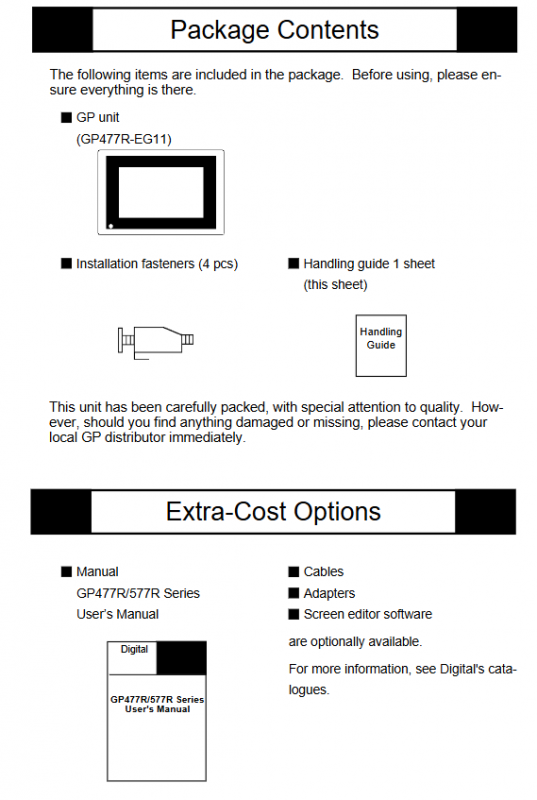
Packaging and Components
Project Content
Host GP477R-EG11
Installation and fixing of accessories x 4, operation guide x 1
Optional parts manual, cables, adapters, screen editing software
Component Description
A: EL high brightness display screen; B: Touch panel; C: Green power light
D: Power terminal; E: AUX auxiliary IO; F: serial port; G: Printing port; H: Tool interface
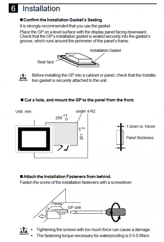
Appearance and installation dimensions
Exterior dimensions: 274 × 216 × 56.5mm
Panel opening: 259 × 201mm (R2 chamfer)
Panel thickness: 1.6-10mm
Installation requirements: Waterproof gaskets must be used, with a fixed torque of 0.5-0.6N · m
Interface definition (key)
1. Serial port (25 pin D-Sub)
Support: RS-232C/RS-422
14 pins: VCC 5V ± 5%/0.25A (external power supply, unprotected)
Recommended connector: OMRON XM2A-501
2. AUX interface (15 pin D-Sub)
Pin signal function
1-8 TSW0-TSW7 touch switch output
9 RUN operation output
10 ALARM system alarm output
11 BUZZ buzzer output
12 DC24V output common terminal
13 AIN-C input common terminal
14 AOUT-C output GND
15 RESET remote reset input
3. Printing interface (14 pins)
Parallel printing signals (PSTB, PDB0-7, BUSY, Initiat, GND)
Prohibited from connecting pins 12 and 13
4. Power terminal
L: Frontline; N: Zero line; FG: Chassis grounding
Wiring and grounding specifications
Power wiring
Use ring terminals with sleeves, with a maximum wire diameter of 2mm ²
Independent circuit breaker control, FG must be grounded
Grounding requirements
FG independent grounding, grounding resistance * * < 100 Ω**
Line protection
Separate wiring for power and signal lines
Use shielded wires to interfere with the environment, with the shielding layer grounded at one end
Install a surge absorber and keep the power cord as short as possible
Environment and Maintenance
Environment: Temperature and humidity within specifications, dust-proof, direct sunlight proof, and chemical gas proof
Cleaning: Do not use diluents/organic solvents, wipe with a soft cloth
Touch control: Do not use hard objects to hit or press forcefully
Key issues
Question 1: What are the power supply requirements for GP477R-EG11? What safety operations must be followed when wiring?
Answer: The power supply is AC100V and only supports this voltage; Before wiring, the power must be completely cut off, FG grounding must be connected, and ring terminals that meet specifications must be used. The torque should be controlled at 0.5-0.6N · m. Live operation and disassembly are strictly prohibited.
Question 2: What are the core functions of the AUX 15 pin interface? Under what circumstances will the ALARM pin output?
Answer: The core functions include touch switch output, operation status output, system alarm output, buzzer output, and remote reset input; ALARM outputs when there is a hardware alarm (memory verification error) or software alarm (system error).
Question 3: What are the absolutely prohibited behaviors during the use and installation of this device?
Answer: It is prohibited to disassemble, modify, or replace internal batteries by oneself; Prohibited from use in flammable gas environments; Prohibit using touch control for emergency stop/life safety/disaster prevention scenarios; Prohibit use in environments with excessive temperature and humidity, strong light, high dust, or chemical substances; Do not hit the touch panel with hard objects.