PILZ PDP67 F 4 code operation instructions
Product Fundamentals
Scope of application
Applicable to PDP67 F 4 code (773603) and PDP67 F 4 code VA (773613), including functionality, installation, wiring, debugging, parameters, and ordering information.
Product core positioning
IP67 protection level distributed passive distributor, used in harsh industrial environments, integrates PSENcode/PSENSlock/PSENini safety sensors into the Pirci safety control system.
Standard Configuration
Module body, PDP67 Connector cs power adapter, 5 labels, 4 blind plugs.
Safety requirements
correct usage
Only used to specify the connection between sensors and control systems; It is prohibited to modify, exceed specifications, or use beyond the environment.
Personnel Requirements
Installation, debugging, and operation must be carried out by qualified personnel who have received training and possess safety knowledge.
Responsibility and Abandonment
Damage caused by unauthorized use renders warranty and liability invalid; Waste disposal follows local electronic waste regulations.
Warning level
Five level identification of danger/warning/attention/prompt/information, distinguishing between personal injury and equipment damage risks.
Structure and Interface
Appearance interface
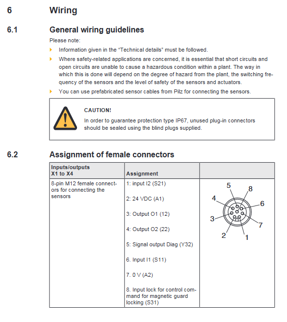
X1~X4: 8-pin M12, connected to sensor
X5: Connected to evaluation equipment
X6: Diag diagnostic output+Lock magnetic lock control
status indicator light
Power: Power status
Diag: Sensor actuator position diagnosis
Lock: Magnetic lock control command status
Installation specifications
Installation method
Flat fixation, secured with 2 M4 internal threads and screws to prevent the shell from being subjected to stress.
protection requirements
Idle connectors must be sealed with blind plugs to ensure IP67 protection.
Mechanical dimensions
Height 120mm, width 60mm, depth 20mm, weight 240g.
Wiring rules
General Requirements
The safety circuit must ensure that short circuits/open circuits do not trigger danger, and priority should be given to using Pilz prefabricated M12 cables.
Interface Definition (Core)
|Interface | Core Functions|
|X1~X4 | Sensor connection, 8-pin M12, including 24V, 0V, I1/I2 input, O1/O2 output Diag、Lock|
|X5 | Connected to evaluation equipment, pin 7 is 0V common ground|
|X6 | 1-4 feet: Diag diagnosis; 5~8 pins: Lock control command|
Connection topology
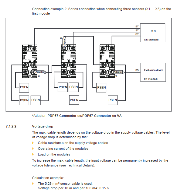
Independent circuit: A single module can connect up to 4 sensors, and the evaluation device is connected to the last available port.
Serial connection of modules: the end port of the former module is connected to the end port of the latter module X1, and a special adapter is required. Pay attention to the voltage drop.
Voltage drop calculation
Affected by wire diameter, current, and length; Example: A 0.25mm ² cable with a voltage drop of 0.15V per 10m/100mA can be compensated by increasing the input voltage appropriately.
Operation and Diagnosis
Ready conditions
The constant power LED indicates that the module is working properly.
Meaning of LED status
|LED | Status | Meaning|
|Power | Always on | Device ready|
|Power | Off | Not powered on/Fault|
|Diag | Always on | The actuator is within the response range|
|Diag | Off | The actuator is not within the response range|
|Lock | Always on | The lock control command is valid|
|Lock | Off | Invalid lock command|
Technical parameters
Project parameters
Supply voltage 24VDC
Load capacity 2A
Protection level IP67 (housing and terminals)
Working temperature -40 ℃~+60 ℃
Storage temperature -40 ℃~+70 ℃
93% RH at 40 ℃, allowing for short-term condensation
Connecting 8-pin M12, made of stainless steel material
Certification CE, cULus Listed
Ordering Information
module model
PDP67 F 4 code:773603
PDP67 F 4 code VA: 773613 (V2A ring nut)
accessories
Adapter: 773610, 773612 (VA version)
M12 cable: 2/5/10/20/30m
Key questions and answers
Question 1: What are the core uses and usage restrictions of this module?
Answer: The core purpose is to serve as an IP67 distributed passive distributor, connecting PSENcode/PSENSlock/PSENini sensors to the Pilz control system in harsh industrial environments. Usage restrictions: Modification and use beyond specifications are prohibited, and must be operated by qualified personnel. Idle interfaces must be sealed to maintain IP67.
Question 2: What is the correct wiring method for sensors and evaluation devices? What are the risks of connecting incorrectly?
Answer: Sensors must be sequentially connected to X1~X4, and evaluation devices must be connected to the last available interface (X2~X5). Risk of incorrect connection: If the assessment equipment is connected before/between sensors, it may cause all subsequent sensors to fail, resulting in the loss of safety functions and potentially causing personal injury or death.
Question 3: What are the key points to pay attention to when connecting modules in series?
Answer: 1 Connect with a special adapter, and connect the end of the previous module to the end of the next module X1; 2. The voltage drop must be calculated to ensure that the terminal voltage is not lower than the allowable value; 3. The evaluation device still needs to be connected to the last idle port of the entire link; 4. Series connection will increase power outage delay, please refer to the sensor manual.