Aerotech UNIDEX 100/U100i single axis motion controller
Product Overview
System composition: Controller hardware+UT100 upper computer software+various optional accessories.
U100: Control board+power board integrated, directly driving the motor;
U100i: Pure control board, outputs analog commands to external power amplifiers.
Ordering model series:
U100M/U101M: Microstep drive;
U100S/U101S: DC servo;
U100Z/U101Z: Brushless servo.
List of supporting motors: stepper, DC servo, brushless servo motor models, torque, speed, bus voltage, fuse specifications.
Optional accessories: Handheld terminal HT, Joystick handwheel, Thumbwheel digital dial, LED digital display IEEE‑488 (GPIB)、 Rotary to digital conversion R/D board, INT isolation I/O expansion board.
Safety warning: Power off before wiring; Keep the sports equipment away from personnel; Prevent static electricity from damaging the board.
Getting Started
Unpacking and electrostatic protection: check for transportation damage; The board must be equipped with an anti-static wristband, and touching the chip pins is prohibited.
Minimum hardware environment for PC: 80486 and above CPU, 4MB memory, EGA/VGA, 4MB hard drive, DOS5.0+ / Windows3.1/95。
Hardware wiring
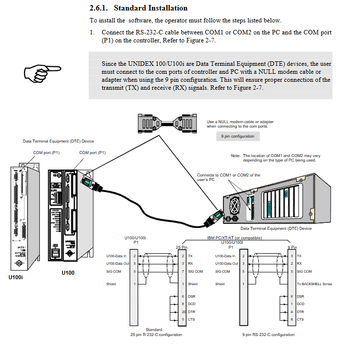
RS-232 uses an empty modem cross cable to connect the PC-COM port to controller P1;
U100 connected to motor, encoder, and limit; U100i is connected to an external BA amplifier.
software installation
Modify CONFIG.SYS/CONFIG-NT to load ANSI.SYS;
Copy the UT100 software from the floppy disk and run com_100.exe COMx to establish communication.
UT100 main menu:
A-File file file editing; B-Run runs the program; C-MDI manual command; D-Status status monitoring; E-Control control; F-Misc miscellaneous items.
Example program 1) Simple trapezoidal motion: Set acceleration and deceleration T, speed V, distance D, GO to execute the motion; 2) Reciprocating motion cycle; 3) Dual task multitasking demonstration: Task 1 runs the motor back and forth, while Task 2 runs the screen counter simultaneously.
Support parallel execution of dual task Task1/Task2.
Hardware Configuration and Interface Description
3.1 Connectors (U100 and U100i have most of the same interfaces)
P1 COM port (RS-232, can be changed to RS-422): connects to PC and handheld terminal HT, providing 5V power supply to HT.
P2 I/O port (37 pin D-SUB)
Optocoupler isolated digital input/output;
1 analog input ± 10V, 1 analog output ± 10V, 8-bit resolution.
P3 encoder/limit/Hall (25 pin D-SUB)
Main incremental encoder SIN/COS/MKR differential signal;
Positive and negative hard limit, Home origin;
Brushless motor Hall sensor input.
P4 auxiliary encoder (9-pin D-SUB): The second encoder is used for dual loop and handwheel input.
Expansion slot Option Bay: Install R/D rotary converter board, IEEE488, INT-I/O board, and dial/display interface board.
U100 exclusive: motor power terminal block, power switch, fuse;
Unique to U100i: AMP feedback connector, compatible with external BA amplifiers.
3.2 U100 panel LED status light
Shun Active: The discharge resistor is working;
Drive Fault: Drive fault (overcurrent, short circuit);
Marker: Encoder Z index pulse;
Reset: Power on/external reset;
Control Fault: Feedback error, program running error;
Remote: Remote mode of the upper computer;
In Position: In place, the axis reaches the target position;
Overload: Overload (position error, speed error, overcurrent);
+Limit/- Limit: Triggered by positive and negative hardware limits.
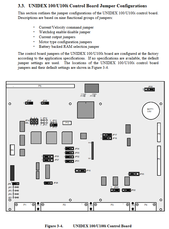
3.3 motherboard jumper configuration
JP8: Current/speed command mode;
JP13/JP18/JP19: Selection of output current range;
JP16/JP17: Motor type (brushed, brushless, stepper);
JP34: Firmware download BOOT jumper.
3.4 U100 power board
Select 100/115/230VAC for AC input jumper; Multiple sets of fuses: motor fuse F1, AC incoming line F2, 5V F3, discharge F4; supports external transformer to modify DC bus voltage.
3.5 Detailed Description of Optional Hardware Accessories
HT handheld terminal: RS232 local operation, editing, running programs, and viewing status.
Joystick joystick: analog input, proportional speed regulation, teaching positioning.
Thumbwheel digital dial: panel input numerical value, read through port variable PV; Supports 2 dials.
6-digit LED digital display: output position, variable value, write port variable PV driver.
R/D Resolver Digital Converter Board: Supports rotary transformers/inductive synchronizers; 12/14/16 bit resolution; Support high-speed automatic resolution reduction mode to increase rotational speed.
INT expansion I/O board: docking with OPTO22 PB series isolated I/O rack, large-scale expansion of digital I/O; supports interrupts.
IEEE-488 (GPIB) interface board: GPIB bus control, supports SRQ service requests.
Software Installation and Interface (UT100)
UT100 software menu functions:
File: Create/edit PGM programs, MAC macros, DEF parameter definitions, CAM cam files;
Run: Select Task1/Task2 and run in Auto/Block mode;
MDI: Manual execution of a single instruction in real-time;
Status: Sports status, general system status, memory, firmware version viewing;
Control: Limit reset, task stop;
Misc: Delete/copy/archive files, parameter setup configuration.
File type:
PGM: Main Program; MAC macro; DEF parameter configuration; CAM cam trajectory; Compile and output the LST list.
Handheld terminal HT operation process.
Programming Command Set
Dual tasking and multitasking operating system: Task 1 and Task 2 are scheduled on a time-sharing basis and run independently; Task lock LOCK;
Interrupt and Exception Processing: Rich mask registers (Invert, Latch, Disable, SRQ, Freeze, Task Mask, Direction Mask) used for limit, fault, and external interrupt response;
Service Request SRQ: Report the event to the upper computer.
Complete command library (dozens of entries):
Motion: A acceleration and deceleration, V speed, D distance, T ramp time, GO start motion, HM hardware zeroing, ABSL absolute mode, INCR incremental mode, GEAR electronic gear, CAM cam, DW dwell delay;
Program flow: IF/ELSE/ELSEIF, GOTO, GOSUB, MAC macro BEGIN‑END、ENDMAC、ENDSUB、EXIT;
Mathematics: ABS, SIN, COS, SQRT, addition, subtraction, multiplication, division, and/or XOR;
IO and Communication: GC character reading, PM message printing, DAC/ADC digital to analog/analog-to-digital conversion;
Automatic tuning TUNE;
Variable system: BV (base variables), FV floating-point variables; Integer 24bit/48bit, floating point number.
Parameter PRM Parameter Set
Parameter number PRM: XXX, divided into 4 categories:
Communication parameters PRM: 001-041RS-232, IEEE-488 configuration, Daisy Chain daisy chain, SRQ request, task initiation program, status display format.
Trajectory generation parameters PRM: 100-163 user unit scaling, ramp time, S-curve, in place tolerance, origin search parameters, soft and hard limits, external interrupt configuration, spline SPLINE interpolation complete set of parameters, cam CAM configuration.
Drive motor parameters PRM: 200-241 step: operating current, holding current, step loss detection, damping; Servo: Kp Ki Kpos Kf PID gain, feedforward, current limiting, position/velocity error trap; Electronic gear GEAR mode; Brushless motor commutation configuration; Axis calibration and backlash compensation.
System underlying parameters PRM: 300-334 update cycles for each loop (servo loop, encoder, R/D converter, fault mask), buffer memory allocation, and error status mask configuration.
Register and Variable REG Register
REG: XXX hardware register, divided into:
Communication registers: BIT input/output, timer, RS-232 queue, IEEE488 bus status;
Motion register: encoder count value, speed, latch position;
Driver registers: instruction position, feedback position, current instruction, position error, speed feedback;
System status registers: motion status, error status, axis status;
Register readable/partially writable, used for real-time reading of hardware status by programs.
Example Program
Provide example source code that can be directly used:
Trapezoidal motion, IO output during motion; dial input distance; LED display;
Handheld terminal operator input; Multitasking; Data recording during operation; Master-slave following; Proportional control of joystick;
External interruption to modify motion trajectory; Encoder counter operation; IEEE 488 communication examples (HP85, QuickBASIC).
Technical Hardware Details
U100 power board and control board frame diagram;
Complete wiring of brushed DC, stepper, and brushless motors;
Encoder, limit, Hall electrical specifications;
RS-232/RS-422 wiring;
I/O port electrical parameters (optocoupler input/output, analog IO);
U100i amplifier feedback connector pin.
Troubleshooting TROUBLESHOOTING
Three major types of fault tables:
Installation, power on, communication failure;
Motor related faults (non rotation, shaking, overload, step loss);
Various types of drive faults, limits, and errors; Provide the phenomenon, root cause, and troubleshooting steps.
PID Loop Tuning
The physical meanings of the PID parameters Kp/Ki/Kpos/Kf for each gain;
Tuning steps; The impact of parameter changes on system stability, overshoot, and response;
Key points for configuring speed feedback signals.
Host Mode Operation
Without the UT100 interface, external upper computers (such as C/BASIC) can directly control the controller through RS-232/IEEE 488 protocol:
Running PGM, instant commands, file upload and download;
Read and write parameter PRM; Read and write register REG; Read and write variables; Task control; Clear the limit.