Aerotech Ndrive MP Ultra Compact PWM Digital Servo Driver
Product Introduction
1.1 Basic Electrical Specifications (MP10)
Project parameters
Motor power supply DC 10-80VDC; Peak 10A (1s), continuous 5A RMS
Control power supply DC 24-80VDC (independent control power supply, achieve Keep Alive, emergency stop can retain communication and feedback), maximum 1A
PWM switching frequency 20 kHz; Maximum bandwidth of servo loop 2500Hz; efficiency 85-95%
Minimum load inductance 0.1 mH @ 80VDC
Support motor brushless servo, brushed DC, two-phase stepper motor
Hardware protection output short circuit, peak overcurrent, RMS overcurrent, bus overvoltage, overheating, control power undervoltage, power stage bias undervoltage; Control – Power side optocoupler+transformer isolation
Encoder onboard output+5V/500mA, providing power to encoder and limit switches
Cooling instructions: The manual provides power consumption output current curve and ambient temperature power consumption curve. High power consumption conditions require the installation of a cooling substrate or fan; The shell temperature can exceed 70 ℃.
1.2 Mechanical Physics
Dimensions: Width 41.1mm, height 141.2mm; M3.5 screw installation;
Weight: Standard 0.454 kg; with IO board/MXU board 0.544 kg;
Installation space: Reserve 25mm of ventilation around the perimeter, and 100mm of operating space on the wiring side, supporting DIN rail installation (with DIN buckle option).
Environment: Working at 0-50 ℃; Storage -30~85 ℃; Humidity ≤ 80% RH non condensing; Altitude ≤ 2000m; indoor use, pollution level 2.
1.3 Onboard hardware resources (without IO board)
Communication: Two FireWire channels (J101/J102); The main body has no RS232 debugging port and no Ethernet.
J103 (25 pin D-SUB motor feedback): Main encoder, Hall sensor, PTC motor thermistor, CW/CCW limit, Home return to zero, encoder fault input, main body 1-channel 12 bit differential analog input AI0.
TB101: ESTOP emergency stop signal detection input (5-24V, signal detection only, power not cut off).
TB102: Motor power output A/B/C, motor DC bus input.
TB103: Independent DC control power input.
LED status lights: CTL power supply, ENA enable, FAULT fault, MRK zero mark.
1.4 Ordering Options
Function Description of Options
IO expansion IO board: 8 isolated DI, 8 isolated DO; 1 12 bit differential AI, 1 16 bit AO; Solid state brake relay; J201 auxiliary encoder channel (PSO must rely on IO board)
MXU simulates the interpolation of sine and cosine encoders, with a maximum of 1024 (4096 after orthogonal); Cannot output orthogonal signals after doubling; Mutually exclusive with PSO, both cannot be enabled simultaneously
PS MP DIN rail DC power supply, capable of driving up to 4-axis MP, with 48VDC output and power levels of 120W/240W/480W; Equipped with brake power supply option.
Important limitation: MP does not support DUAL/TRUPLE-PSO, RDP rotary transformers, or Ethernet. The PSO output must rely on the J201 auxiliary encoder interface on the IO board.
1.5 Compliance Certification
CE(EMC 2014/30/EU、LVD2014/35/EU、RoHS2); TUV‑SUD NRTL UL61010‑1; As a complete machine component only, the final equipment requires EMC testing of the entire machine.
Installation and wiring configuration
2.1 FireWire Bus Configuration
Dial S1 to set the unique device address 1-32 for the driver, corresponding to the A3200 axis number one by one;
A maximum of 16 drives per daisy chain; The maximum number of axes for the entire machine is 32; Copper cable with a maximum length of 4.5 meters, using fiber optic FireWire repeaters for long distances;
Support mixed networking with Ndrive HP, HPe, CP, HLe, CL, ML full range drives.
2.2 Two independent DC power sources
MP must be connected to both the control power supply TB103 (24-80VDC) and the motor power supply TB102 (10-80VDC) to function properly.
TB103 control power supply: After the emergency stop cuts off the motor power supply, this circuit does not cut off power, maintaining FireWire communication and encoder power supply; Input requires series connection of fuses; The cable needs to be fitted with a designated ferrite magnetic ring to reduce radiation interference.
TB102 motor busbar+motor three-phase output A/B/C; Ferrite magnetic rings are also required; Reliable grounding protection is necessary.
External power supply scheme: TM3 transformer module, PS-MP series DIN rail DC power supply, with up to 4 MPs sharing one set of power supply.
2.3 Mandatory EMC cabling requirements
All motor cables and feedback cables use shielded cables, and the metal D-SUB shell is crimped and shielded;
Power cables and encoder/IO signal lines are physically separated and routed separately;
Install Aerotech designated ferrite beads on the motor and FireWire cable.
2.4 Motor wiring and phase setting
Support brushless, brushed DC, two-phase stepper motors; The original motor cables are used directly, and third-party motors must be phase modulated. There are two methods of phase modulation:
Live phase modulation: A3200 configuration manager’s motor phase calculator, Nstat software real-time monitoring of Hall status;
Power off oscilloscope phase adjustment: measure the back electromotive force and Hall timing of the motor, and check the phase alignment.
Brushless motor: three-phase A/B/C output, Hall HA/HB/HC connected to J103; Hall all 0 or all 1 reports Hall fault.
Brushed DC motor: motor connected to A/C terminal, B vacant; Check the polarity of the back electromotive force of the manual motor to determine the positive direction.
Two phase stepper motor: winding connected to A-B C; The encoder must verify the phase.
2.5 J103 (25 pin D-SUB motor feedback) key signal
Encoder: Standard RS-422 TTL differential; MXU options support analog sine and cosine encoders; Onboard+ 5V@500mA Encoder power supply.
Hall input (brushless motor).
PTC motor thermistor: Resistance>1k Ω triggers motor overheating fault.
CW/CCW positive and negative limit switches, Home reset switch; The software supports normally open/normally closed; Reverse limit connection phenomenon: It is possible to collide with the limit, but it cannot be reversed to exit.
Encoder fault input;
Body simulation input AI0 (differential ± 10V, 12 bits);
Output pins of onboard solid state relay for holding brake (can directly transmit the holding brake signal in the feedback cable).
2.6 TB101 ESTOP emergency stop input
Only state detection input, cannot cut off the motor power circuit!
5-24V input, only reporting faults to A3200;
A truly safe shutdown requires an external relay to disconnect the TB102 motor DC bus; TB103 controls the power supply to remain powered on;
Axis parameter FaultMask enables ESTOP fault; Relay coils must be connected in parallel with RC networks or varistors to absorb surges.
2.7 Quick Installation Process
1) Set S1 device address; 2) Connect motor power+motor feedback; 3) FireWire bus; 4) IO board IO (optional); 5) Control power supply TB103; 6) Motor power supply TB102; 7) Connect to ESTOP (optional).
IO expansion board
When not equipped with IO board: The MP body does not have digital DI/DO and auxiliary encoder, so PSO cannot be used.
Interface resources
TB201: Solid state relay for holding brake (24VDC, maximum 2.5A); Onboard+5V/0.5A user power supply; Choose between the brake output of motherboard J103 and the brake relay of IO board TB201, and do not use them simultaneously.
TB202: Analog IO; 1-channel differential 12 bit AI1 (± 10V); 1 channel of 16 bit AO1 (-5~+5V).
TB203 Opto In: 8-channel optocoupler isolated digital input, divided into two independent common terminals, supporting source/sink wiring.
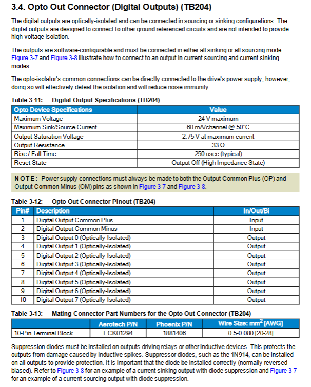
TB204 Opto Out: 8-channel optocoupler isolated digital output, maximum 60mA per channel; inductive load (relay) must be connected to a current diode.
J201 (9-pin D-SUB, key): Auxiliary encoder channel/PSO output (multiplexed hardware, choose one)
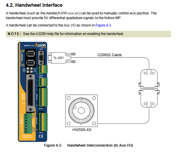
As input: connected to external encoder, electronic handwheel, master-slave following dual closed loop;
As output: PSO position synchronization output (laser triggered); After configuring the PSO command, the hardware automatically switches to output and the onboard terminal resistor is removed;
PSO specifications: maximum single axis tracking rate of 16.6 MHz, maximum output of 12.5 MHz; Typical delay of 160 ns; RS-422 differential output, external optocoupler isolation is recommended for long distances;
Hard mutual exclusion: Enable MXU encoder interpolation option, PSO function is not available.
J201 cannot simultaneously perform encoder input and PSO output; All SIN/COS/MRK pins must have a unified direction.
Accessories
Complete set of supporting cable part numbers: motor cable, feedback cable, FireWire copper cable/fiber optic cable.
Joystick joystick: connected to IO board analog input, used for manual inching, supports single axis/dual axis joystick.
Electronic Handwheel: Differential RS-422 output, connected to IO board J201 auxiliary encoder port.
Maintenance
Control board fuse: F1 control power supply 2A; F2 motor busbar 5A;
Definition of LED indicator lights: CTL power supply, ENA enable, FAULT fault, MRK marking pulse;
Preventive maintenance: monthly inspection; Clean the ventilation vents for heat dissipation; Tighten the connector; Check for cable wear and tear; After power failure, wipe the housing with a dry cloth or a small amount of isopropanol. It is strictly prohibited for liquid to flow into the connector.