Fuji FRENIC Mini Inverter
Product Overview
Applicable Models
Three phase 200V: FRN0001~0020C2S-2 (0.1~3.7kW)
Three phase 400V: FRN0002~0011C2S-4 (0.4~3.7kW)
Single phase 200V: FRN0001~0012C2S-7 (0.1~2.2kW)
Core purpose
Small fan, water pump, conveyor belt, compressor, simple mechanical speed regulation
Support AMF self start stop, PID regulation, multi-stage speed, external terminal control, RS485 communication
Key Features
Small size, high protection, low cost, high reliability
Support V/F control, dynamic torque vector control, PMSM drive
Complete protection: prevention of overcurrent, overvoltage, undervoltage, overload, overheating, and stall
Panel buttons+potentiometer speed control, supporting external terminals and communication control
Safety regulations (mandatory reading)
Warning level
Warning: May cause death/serious injury
CAUTION: May cause minor injuries/equipment damage
Core taboos
Prohibited for use in single-phase motors and life support systems
Must be installed with metal and kept away from flammable materials
Grounding is required, and MCCB/ELCB circuit breakers must be added to the input
Do not connect the power supply to the output terminal U/V/W
Prohibit adding surge absorbers and compensating capacitors on the output side
Power off for at least 5 minutes and confirm that the DC voltage is less than 25V before disassembling the machine
The STOP button on the panel can be blocked and must be externally connected for emergency stop
Installation and Environment
Environmental Requirements
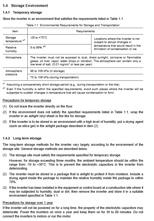
Temperature: -10~+50 ℃ (when there is no gap in parallel -10~+40 ℃)
Humidity: 5~95% RH (no condensation)
Altitude: ≤ 1000m (1000-3000m requires derating)
Protection: IP20, indoor installation, dustproof and oil proof
Installation spacing
Up and down: ≥ 100mm; left and right: ≥ 10mm
Multiple units can be arranged side by side without gaps; Stacking up and down requires the addition of insulation panels
Wiring (Core Chapter)
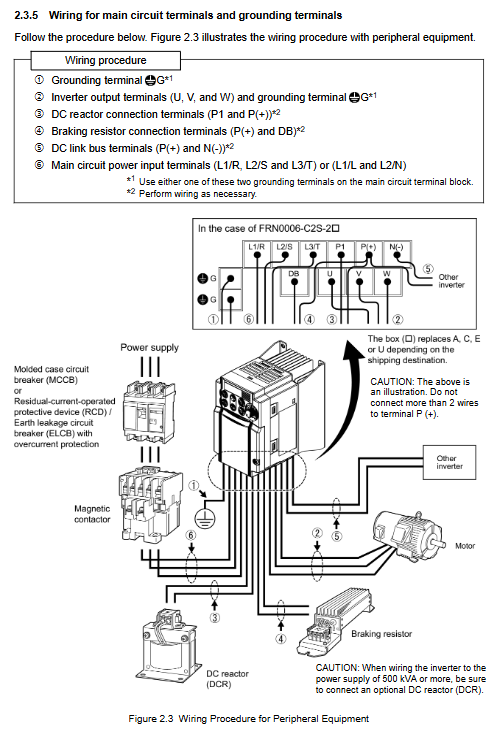
Main circuit terminal
Input: L1/R, L2/S, L3/T (three-phase)/L1/L, L2/N (single-phase)
Output: U, V, W → connected to motor
DC circuit: P (+), N (-), P1, DB (braking resistor)
Grounding: The G terminal must be grounded
control terminal
Digital inputs: FWD/REV, X1/X2/X3, CM, PLC
Analog inputs: 12 (0-10V), C1 (4-20mA), 11 (AGND)
Analog output: FMA (0-10V)
Transistor output: Y1, Y1E
Relay output: 30A/30B/30C
Communication: RJ-45 (RS485)
Wiring rules
The input power must be connected to L1/L2/L3, and it is strictly prohibited to connect to U/V/W
Motor wire ≤ 50m, extra long requires an output filter OFL
Separate the wiring of the main circuit and control line, and ground the shielded wire
Power supply ≥ 500kVA must be connected to DC reactor DCR
The braking resistor should only be connected to P (+) – DB, and it is strictly prohibited to connect to P-N
Jumper settings
SW1: Digital Input SINK/Source Switching
SW3: RS485 terminal resistor ON/OFF
Panel operation (three major modes)
Panel buttons
RUN: Run
STOP: Stop
PRG/RESET: Programming/Reset
FUNC/DATA: Function/Data
▲/▼: Parameter adjustment
three modes
Operation mode: monitoring frequency, current, voltage PID
Programming mode: parameter setting, data check, I/O check, alarm query, maintenance information
Alarm mode: Fault code display, historical records, fault data
Common Operations
Potentiometer: direct speed regulation
▲/▼: Digital setting frequency
PRG → Enter Parameters
STOP+▲: Jogging mode
Function code system (8 categories)
1) F-code: Basic functions (most commonly used)
F01: Frequency command source (panel/potentiometer/terminal/communication)
F02: Running instruction source (panel/terminal)
F03: Maximum frequency
F04: Reference frequency
F05: Reference voltage
F07/F08: Acceleration and deceleration time
F09: Torque Enhancement
F10-F12: Electronic thermal relay (motor overload protection)
F14: Power outage restart mode
F20-F22: DC braking
F26: Carrier frequency (noise reduction)
F42: Control mode (V/F/vector/PMSM)
2) E code: Terminal function
E01-E03: X1-X2-X3 Function Definition (Multi speed, Reset, Jogging, DC Braking, etc.)
E20/E27: Y1/30A Output Definition (Running, Frequency Arrival, Alarm, Overload Warning)
E52: Panel menu mode (simple/full function)
3) C code: frequency control
C01-C99: Jump frequency, multi-stage speed (16 stages), jog frequency PID
4) P code: Motor 1 parameters
P02-P03: Motor capacity/rated current
P04: Automatic tuning (stationary/rotating)
P60-P63: PMSM permanent magnet synchronous motor parameters
5) H-code: Advanced Features
Automatic reset, fan control, S-curve acceleration and deceleration, instantaneous power outage restart, maintenance timer
6) A code: Motor 2 parameters (dual motor switching)
7) J code: Application Function (PID)
J01: PID Enable
J03-J05: PID proportional/integral/derivative
8) Y-code: Communication (RS485)
Y01: Station number; Y04: Baud rate; Y10: Protocol (Modbus RTU)
Run and debug
Test steps
Confirm correct wiring and reliable grounding
Set the rated parameters of the motor (F04/F05/P02/P03)
Set acceleration and deceleration time
Low speed (5Hz) test run, confirm steering
Gradually increase the speed and check for vibration/noise/current
Automatic tuning (P04)
Mode 1: Static tuning (resistance/leakage impedance)
Mode 2: Rotation tuning (no-load current/slip)
It is essential to adapt to third-party motors.
Protection function (alarm and trip)
Main alarm code
OC: Overcurrent
OV: Overvoltage
LU: Undervoltage
OH: Overheating of heat sink
OL: Motor overload
EF: External malfunction
Erx: Communication/parameter error
Third level action
Warning: Do not stop the machine
Uninstalling: Jumping output without interruption
Alarm: Shutdown and Trip
Maintenance and Inspection
routine inspection
Temperature, noise, vibration, cooling fan, terminal fastening
Regularly replace parts
Electrolytic capacitors, cooling fans, relays
insulation test
Use a 500V megohmmeter, perform disassembly testing, and prohibit online testing
Standards and Certification
Compliant with the EU LV Low Voltage Directive and EMC Directive
Harmonic suppression suggestion: Install DC reactor DCR
It is recommended to use B-type or high-frequency corresponding type for leakage protection devices
Typical application configuration
Panel control: F01=4 (potentiometer), F02=2 (forward rotation)
Terminal two speed: X1=SS1, C05=30Hz, C06=50Hz
PID constant pressure water supply: J01=1, C1=4-20mA feedback
RS485 Modbus:y01=1,y04=9600,y10=0
Braking and parking: DB is connected to the braking resistor, F20=0.5Hz,F21=50%