Allen Bradley MicroLogix 1500 Programmable Controller
Overall positioning of the product
Product Series: MicroLogix 1500 (1764 Controller)+1769 Extended I/O
Type: Small modular PLC, supporting local I/O and Compact I/O expansion
Applicable scenarios: small automation equipment, machine tools, fans and pumps, packaging machines, simple production lines
Processor model:
1764 LSP: Basic Edition
1764-LRP: Enhanced version, dual communication ports
Core hardware composition
1. Host base (3 types)
Model Power Supply Input/Output High Speed I/O
1764-24AWA 85-265V AC 12 × 120V AC 12 × Relay None
1764-24WBA 85-265V AC 12 × 24V DC 12 × Relay 4-channel high-speed input
1764-28BXB 20.4-30V DC 16 × 24V DC 6 Relay+6FET 8 In 2 Out High Speed
2. Expansion capability
Support 1769 Compact I/O expansion module
Maximum expansion: 16 modules (divided into two groups, with a maximum of 8 modules per group)
Must be equipped with end caps: 1769-ECR/ECL
Expansion requires independent power supply: 1769-PA2/PA4, PB2/PB4
3. Optional accessories
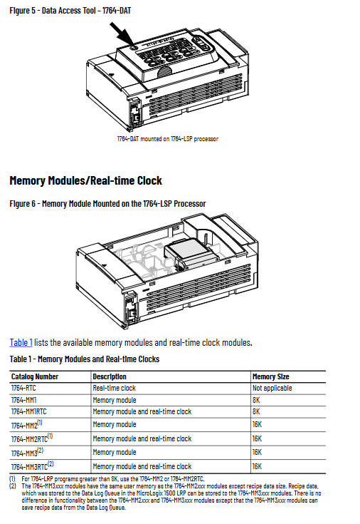
Data Access Panel 1764-DAT: Local Monitoring/Parameter Modification
Real time clock 1764 RTC
Memory module: 8K/16K (with/without RTC)
Lithium Battery: 1747-BA (Program Power Down Save)
Safety and Installation Standards
1. Security level
Suitable for Class I Division 2 explosion-proof environment
Must be installed inside the cabinet and wired in accordance with NEC 501-4 (b)
2. Installation requirements
Recommend horizontal installation, not vertical installation
Reserve a heat dissipation space of ≥ 50mm around the perimeter
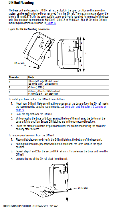
Supports 35mm DIN rail or panel installation
Must be reliably grounded to prevent static damage
3. Precautions for power supply
AC model: 85-265V AC wide voltage
DC model: 20.4-30V DC
Equipped with power on surge current protection and power-off hold (10ms-3s)
Wiring specifications (emphasis)
1. Wiring standards
Wire diameter: 0.5-2.5mm ² (14-20AWG)
Torque: 1.13N · m (maximum 1.3N · m)
Input support: leakage type/source type universal
Output: Relay (passive), FET (active)
2. Key protection
Inductive loads must be equipped with surge suppression
DC load: 1N4004 diode
AC load: varistor or RC absorber
Grounding with 2.5mm ² copper wire
3. Special wiring
ZCT leakage protection: grounding prohibited
4-20mA analog: must shield the wire
It is recommended to install a filter on the output side of the frequency converter
Communication function (most complete part)
1. Standard ports
RS-232 (DB9): All models
Channel 1 (LRP exclusive): Second serial port
2. Support protocols
DF1 full duplex: point-to-point (default 19200bps)
DF1 half duplex: master-slave multi station
DH-485: Rockwell Industrial Network (up to 32 nodes)
Modbus RTU Slave: B series and above support
ASCII: Connect barcode scanner, instrument, printer
3. Network Expansion
AIC+Converter: RS232 ↔ RS485(DH‑485)
ENI Ethernet module: Implementing EtherNet/IP
Supports modems and wireless radio stations
Operation and Tools
1. Data Access Panel DAT
View/modify 48 bits, 48 integers
Display fault codes and operational status
Support F1/F2 custom function keys
Can be plugged and unplugged with power
2. Potentiometer Trimpot
2 adjustable potentiometers (0-250)
Directly used as a set value in the program
3. Mode switch
RUN/PROG/REM three gears
Operation, programming, remote control
Clock and storage function
1. Real time clock RTC
Year Month Day Hour Minute Second, Week
Accuracy: ± 70 seconds/month
Built in battery, low battery warning 14 days in advance
2. Memory module
Backup program, no loss in case of power failure
Support program comparison and write protection
Can be plugged and unplugged with power (not for transmission)
System load and heat dissipation calculation
Provide a complete 5V/24V current calculation table
Base, expansion module, DAT, AIC+power consumption are all listed
Must satisfy
Base 5V: ≤ 2250mA
24V:≤400mA
Provide a formula for heat dissipation power for cabinet heat dissipation design
Fault diagnosis and troubleshooting
1. Meaning of LED status lights
POWER: Power Supply
RUN: Run
Fault: (flashing=program error; constantly on=hardware error)
BAT: Low battery
COMM: Communication Activity
2. Common fault handling
Unable to power on: Check wiring, voltage, polarity
Fault flashing: check for S: 6 fault code
Input no response: Check wiring, filtering, common terminal
Output not functioning: check load, power supply, suppressor
Communication failure: check baud rate, verify, address, mask
3. Fault clearing method
Automatic power on clearing
Fault subroutine clearing
Programming software clearing
Firmware upgrade
Using ControlFLASH software
Switch to default communication mode before upgrading (DCOMM light on)
Upgrading will clear user programs and must be backed up first
Upgrade failure will display a specific LED mode
Specifications and Certification
Working temperature: 0~+55 ° C
Vibration: 5g, Impact: 30g
Certification: UL, CE, UKCA, RCM, Class I Div 2
Relay lifespan: inductive load 2 million times, resistive load 20 million times
FET high-speed output: fastest response of 6 μ s
Replace parts
Lithium battery: 1747-BA
Terminal block: 1764-RPL-TB1/TB2
Dust cover, ESD baffle, communication port cover
All have official Rockwell part numbers