DEIF Multi line 2 Series PPU Unit Power Management (PPM) Operation Manual
Human Computer Interaction System
The entire human-machine system includes three types of operation entrances: a local display screen, an external AOP-2 operation panel, and PC upper software, supporting remote monitoring through multiple communication links.
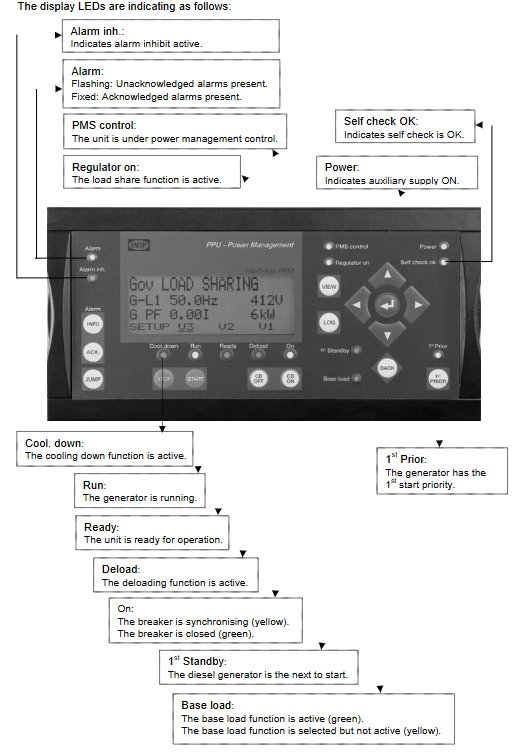
(1) Local display screen buttons and indicator lights
function key
INFO: One click jump to the alarm page;
ACK: Confirm the current activation alarm;
JUMP: Directly enter the parameter channel number to quickly jump to the menu without flipping through pages layer by layer;
VIEW: Switch the first line of the settings interface to display the content;
LOG: Retrieve 150 event sequence records;
Use directional keys to move the cursor left and right, and adjust the setting values up and down; Enter to confirm the selection; BACK returns to the previous level;
Unit operation keys (only effective in semi-automatic mode): START start, STOP stop, CB ON synchronous closing, CB OFF opening;
1st PRIOR: Set the priority for the first level startup of the unit.
Panel LED status light
Covering operation, cooling, unloading, synchronization, bus closing, PMS power management on/off, fault alarm, imbalance, communication transmission and reception, priority and other states, distinguishing between constant light/flashing to represent different fault/operation states.
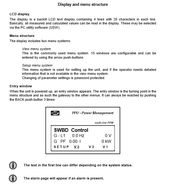
Display screen: 4-line x 20 character backlit LCD, divided into two independent menu systems: View menu (daily monitoring) and Settings menu (parameter tuning); Default homepage when powered on, automatic pop-up alarm in case of malfunction.
View menu V1/V2/V3: Real time viewing of operational data, customizable display of voltage, current, power, frequency, load distribution, and circuit breaker status;
Set menu hierarchy: PROT protection, CTRL control, I/O input/output, SYST system four sub menus, password required to modify parameters (factory 2000), automatically locked after 3 minutes of inactivity.
(2) External AOP-2 expansion operation panel
Remote operation unit outside the cabinet, connected to the host through an internal CAN bus, with a maximum distance of 500 meters; Equipped with 16 status LEDs and 8 function buttons, it is compatible with four power station topologies (pure diesel unit, with shaft generator, with shore power, and segmented busbar), supporting mode switching, light and heavy load switching, and light self checking.
LED covers semi-automatic/automatic, shaft generator/shore power, segmented busbar, overload request, PMS lockout, non critical load trip, unit trip, shutdown alarm and other states; The button can switch the operating mode, switch the safety standby unit, and perform full light inspection.
(3) PC upper level tool software
DEIF dedicated debugging software, connected to controllers through USB, RS485, fiber optic, Ethernet, and cellular modems, with core functions:
Unit overview interface: Real time display of voltage/frequency/power/circuit breaker/regulator status, number of activated alarms;
Historical alarm: with timestamp, distinguishing confirmed/unconfirmed, current/past faults;
Trending curve: long-term plotting and monitoring of voltage, current, power, and frequency;
Parameter upload/download, batch configuration, real-time IO status viewing, firmware upgrade, system clock synchronization;
Support custom views, input/output text renaming, and exporting complete event logs.
(4) System operation mode
Semi automatic SEMI-AUTO: manually issuing start stop and opening/closing commands, the controller automatically synchronizes and adjusts the load;
Fully automatic AUTO: The system automatically increases or decreases units, distributes loads, and trips light and heavy loads based on the total load;
Additional dedicated modes: shaft generator mode, shore power mode, busbar segmented SPLIT mode;
Safe backup SECURED: Automatically increases the machine to ensure power supply during heavy load, and can be manually switched on or off.
(5) Additional general functions
Custom view configuration: Display measurement points on the upload/download screen of the upper computer;
JUMP channel direct access function: password, system version, phase compensation and other hidden menu dedicated channels;
3-level password: customer, service, and administrator level permissions.
Alarm List
After the alarm is triggered, an automatic pop-up window will appear, supporting single browsing, jumping to the first/last alarm, and batch confirmation with the ACK button; The alarm entry will automatically clear after the fault disappears, and the unconfirmed alarm will continue to flash as a prompt.
Store up to 150 SOE event sequence records, recording all events such as unit start stop, closing, protection actions, communication failures, analog anomalies, etc., each with precise time stamps.
Complete parameter directory
The manual lists all adjustable parameters in a complete table format, with a unified format: parameter number, name, adjustment range, step size, factory default, technical description, divided by major categories:
1. Generator protection category
Covering multiple levels of protection such as reverse power, multi-stage overcurrent, quick break, high and low voltage, high and low frequency, current/voltage imbalance, reactive power over limit, overload, etc; Each type of parameter includes action setting, delay, enable switch, fault output relay, and fault level (alarm/trip shutdown).
2. Busbar protection category
Multi segment overvoltage, undervoltage, high and low frequency protection of the busbar, used for grid connection/bus tie fault discrimination, supporting only alarm or direct tripping of all units.
3. Non critical load NEL trip protection
Overload, low frequency, and power over limit automatic graded removal of secondary loads, divided into two groups of trip logic, can be switched on or off separately.
4. Synchronous closing related parameters
Static/dynamic synchronization selection, frequency/voltage/phase window, closing delay, synchronization failure, phase sequence error, circuit breaker opening and closing fault criteria.
5. Governor GOV/voltage regulator AVR adjustment parameters
Frequency, active power PID proportional integral, load ramp up and down slope, regulation fault monitoring, detection of actual power deviation exceeding the set limit alarm.
6. Switching input DI
All passive input delays, associated alarms, output relays, custom fault levels, including engine failure, emergency stop, start permission, circuit breaker feedback, etc.
7. Analog input (4-20mA, Pt100, VDO sensor)
Oil pressure, water temperature, liquid level, speed sensors, 4-20mA external transmitter disconnection detection, over limit alarm setting.
8. Speed and battery monitoring
Overspeed level 1/2 protection, high and low voltage alarm of control power supply.
9. Communication parameters
Modbus/CAN bus device address, baud rate, communication fault timeout alarm.
10. Synchronization, power adjustment, and power management logic
Synchronous pressure difference frequency difference window, active/reactive power adjustment, unit startup frequency, frequency loss shutdown delay, cooling shutdown duration, black start parameters.
11 Relay output configuration
All alarm and control relays can be customized with trigger sources, action delays, and normally open/closed logic.
12 4-20mA analog transmission output
Active, reactive, apparent, power factor, voltage, current, frequency transmission, with adjustable range upper and lower limits.
13 Basic System Parameters
Rated frequency, power, current, voltage, CT/PT ratio, system time, running hour count, closing frequency, and multi language switching.
14 Power Management PMS Special Parameters
Number of system units, load start stop power threshold, unit start priority rotation, base load mode, overload load configuration, bus segmentation logic, CAN bus unit communication address management.
Failure Mode and Effects Analysis (FMEA)
A complete comparison table of system faults, fault causes, local actions, final system consequences, detection methods, and system automatic countermeasures, with key faults including:
CAN communication loss: The unit is detached from power management, operates independently in speed and voltage regulation, no longer participates in load distribution, and retains protection functions;
Synchronization closing failure: Lock closing, automatically start standby unit;
Circuit breaker feedback disconnection: Determine that the unit is unavailable and automatically switch to the next unit;
Generator protection tripping: The unit shuts down due to disconnection from the grid, and the system compensates for the load with additional units, posing a risk of overload;
Engine warning/shutdown: first reduce the load and disconnect before shutting down, and automatically start the standby unit.
Supporting communication and networking instructions
Wired communication: USB local debugging, RS485 Modbus, CAN internal bus of the unit, Ethernet;
Wireless expansion: external cellular modem for remote monitoring;
Bus rules: The CAN bus allocates 1-10 unit addresses and supports automatic identification of online devices. Offline addresses need to be manually turned off; Modbus addresses 1-247, supporting broadcast commands.
Hardware matching and environmental supplementation
AOP panel with CAN wiring up to 500 meters away;
The whole machine supports 12/24VDC wide power supply and input overvoltage/undervoltage monitoring;
All relays output a unified capacity standard, analog output active 4-20mA, no external power supply required;
Fault classification definition: 1=alarm only, 3=lockout synchronization, 4=circuit breaker tripping, 6=emergency shutdown of the unit, all protections can be freely assigned fault levels.