ADLINK PXIS-2719A 19 slot 3U PXI chassis
Product Overview and Core Features
Slot configuration: 19 3U slots, Slot1 system controller slot, Slot2 star trigger slot, and the rest are peripheral slots; Supports PXI zero slot controllers with a maximum width of 3 slots, recommended to be paired with Linghua PXI-3950/PXI-3920 controllers.
Cooling system: Rear 3 large flow fans (each 185.9CFM), bottom inlet and rear outlet, each slot has a cooling capacity of 25W (verified in a 55 ℃ environment); The fan supports two modes: AUTO automatic temperature control and speed regulation/FULL full speed.
Power supply: Industrial grade 600W AC power supply, wide AC input 100-240VAC.
Backboard function
Star Trigger (Slot2);
The PXI trigger bus is divided into 3 segments, and the onboard dip switch can be configured with inter segment on-off and signal direction;
Local Bus, interconnecting adjacent slots;
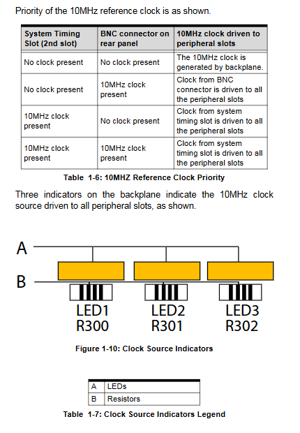
10MHz system reference clock, supporting automatic priority selection of three clock sources;
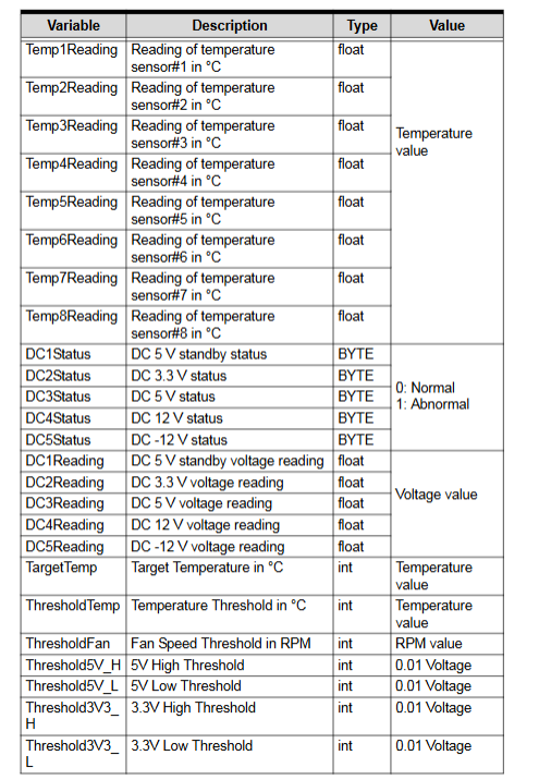
Monitoring capability: 8-channel backplane temperature sensor, three channel fan speed, and five channel DC power rail voltage monitoring; RS-232 serial port enables remote reading of status and remote power on/off; Supporting PC monitoring tool software.
External clock: BNC interface external 10MHz reference clock input.
Important limitation: CompactPCI 3U modules with Rear I/O rear I/O are not supported and may conflict with PXI backplane J2 signals, posing a risk of hardware damage.
Key hardware specifications
Power parameters
Item Parameter
AC input 100-240VAC (working 85-264VAC), 50-60Hz
The maximum DC power of the whole machine is 600W
+5V 45A, Ripple 20mV
+12V 15A, Ripple 50mV
+3.3V 42A, Ripple 20mV
-12V 4.75A, Ripple 50mV
10MHz reference clock
Precision of onboard crystal oscillator: ± 50ppm; The maximum clock offset between slots is 300ps;
External BNC input: 10MHz ± 100ppm, amplitude of 100mVpp~5Vpp, input impedance of 50 Ω;
Clock source priority (from high to low): Slot2 star trigger slot PXI_CLK10-IN → BNC external input on the rear panel → built-in oscillator in the chassis.
Machinery and Environment
Dimensions: 444.4 mm (W) × 177.8 mm (H) × 455 mm (D);
Weight: 14.5 kg; supports rack installation;
Working temperature: 0~55 ℃; Storage -20~70 ℃; Humidity of 10-90% without condensation;
Shock vibration: functional shock 30G; random vibration;
Certification: EN61010-1 safety, EN55011 A-class emission, EN61326-1 electromagnetic compatibility.
Front panel and rear panel interface
front panel
Power boat type switch;
Status LED (from right to left)
Blue Power: Always on=Power supply is normal; Flashing=power rail over limit alarm;
Green Fan: Always on=fan is normal; Flashing=any fan speed below the threshold (default 800RPM);
Amber Temperature: off=normal temperature; Flashing=temperature exceeding threshold (default 70 ℃).
rear panel
AC power input socket;
BNC: 10MHz REF IN external reference clock input;
RS-232 monitoring serial port: cross transmit and receive, requiring a direct serial port cable for remote monitoring;
Fan mode dialing: AUTO (temperature control and speed regulation)/FULL (full speed);
INHIBIT prohibition switch: controls whether the power button on the front panel is activated.
Detailed explanation of backplane architecture
Slot1: System controller slot: PXI standard zero slot, can accommodate up to 3 slot wide controllers, occupying expansion slots to the left.
Slot2: Star Trigger: Provides independent star trigger routing to Slot3-Slot15; When not triggered by a star, it can be used as a regular peripheral slot.
Trigger bus segmentation: The backplane trigger bus is divided into 3 segments: Slot1-6; Slot7‑12; Slot13‑19; The onboard P2-P5 dip switch controls the inter segment buffer and can be configured with isolation and unidirectional forwarding (left → right/right → left) in multiple topologies.
Local Bus: 13 high-speed sideband signals between adjacent peripheral slots; There is no local bus between Slot1 and Slot2.
Hardware installation steps
Packing List
PXIS-2719A chassis, power cord, filler block kit (1 3-channel block+18 single slot blocks), CD, user manual.
Key points for heat dissipation installation
Desktop use retains support foot pads; During rack installation, at least 44.5mm (1U) of space should be reserved for the air inlet at the bottom of the chassis; Leave at least 76.2mm at the rear air outlet;
Unused slots must be equipped with filler plates to ensure air ducts, heat dissipation, and EMC performance.
Module installation
System controller: Insert Slot1, press down the pop-up handle to fully engage the backplane connector, and tighten the panel screws;
Peripheral module: Install PXI/regular CompactPCI module on Slot2-19; It is strictly prohibited to install rear mounted I/O type CompactPCI modules;
Fill all vacant slots with baffles.
Rack installation
Disassemble the handles and rubber foot pads on both sides of the chassis, assemble the rack mounting bracket, and adjust the front and rear positions of the bracket to achieve inward retraction of the chassis.
power on
Universal wide voltage power supply, no need for manual voltage selection; Connect the grounding power cord and press the power button on the front panel to turn on the device.
Chassis system management (remote monitoring)
The chassis is monitored through the RS-232 serial port on the rear panel. The supporting tool is PXISRemoteMonUtil.exe, which is stored in the random CD \ Driver Installation \ PXI Platform \ PXI chassis \ PXIS2719A \ RemoteMon \ directory.
The software function interface is divided into three parts
Connect Control
Select COM serial port and establish connection;
Chassis status log: can set sampling period and save txt logs;
Save/load alarm threshold configuration, restore factory threshold, and read MCU firmware version.
Remote Status&Control
Remote power on/off; The operating system must be shut down before shutting down;
Fan mode: Auto automatic temperature control/Full speed;
Target Temp: Set the temperature corresponding to 100% fan speed, with a default of 50 ℃; The fan gradually increases speed at 25 ℃ and reaches the target temperature at full speed; 70 ℃ is the hardware temperature alarm point;
Alarm threshold: DC voltage upper and lower limits, temperature alarm threshold, fan speed alarm threshold.
Chassis Status (real-time status of chassis)
DC power rail: 5Vsb, 3.3V, 5V, 12V, -12V voltage reading+status;
Readings of 8-channel backplane temperature sensors T1-T8;
Three way fan F1-F3 speed RPM and status.
Secondary development API library
Provide a C language function library and define three key structures:
ChassisStatus: Real time status of the chassis (power supply, fan speed, 8-channel temperature, 5-channel DC voltage);
ChassisSetting: Chassis configuration parameters (target temperature, various alarm thresholds, fan mode);
MCU Version: The firmware version of the microcontroller in the chassis.
Main API functions
Function Function
Initialize serial port COM1- COM8 with InitCOM and return handle
GetChassisStatus reads the real-time status of the chassis
Get threshold to read the current threshold configuration
GetCUVersion reads firmware version number
AKS hassisPowerOn/AKS hassisPowerOff remote power on/off
SetFanSpeedMax/SetFanSpeedAuto sets the fan to full speed/automatic mode
SetTarget Temp: Set the target temperature (25-70 ℃) corresponding to the fan’s full speed
SetFanAlarm/SetTempAlarm/SetXvAlarm Set fan, temperature, and various voltage alarm thresholds
CloseCOM closes the serial port handle
Troubleshooting, Maintenance, and Safety
Common troubleshooting
Unable to power on: Check that the controller and module are fully locked, and that the power cord is well grounded; Pull out all modules first and insert them one by one to locate the faulty module.
Power light flashing: power rail exceeding limit; Remove all modules and determine if there is a module short circuit.
Fan light flashing: Fan speed below 800RPM threshold; Check if the fan is obstructed by foreign objects.
Temperature light flashing: The inside of the chassis is overheated; Check if the baffle is missing and if the air inlet/outlet is blocked.
Maintain
The whole machine weighs 14.5kg and is handled for transportation;
Clean the casing and ventilation filter with a dry cloth after power failure;
Do not connect the power supply to the overload power supply circuit.
Safety Warning
Disassembly and maintenance must be powered off; Stay away from liquids; Ensure ventilation;
Incorrect model of lithium battery inside the chassis may cause explosion;
Only authorized engineers are authorized to perform internal repairs on the chassis.