ADLINK cPCI-6965 series 6U CompactPCI single board computer
Product Overview
1. Product positioning
CPCI-6965 is a 6U specification CompactPCI Industrial Single Board Computer (SBC), available in two panel widths: 4HP single slot and 8HP dual slot. It is equipped with an Intel Core 2 dual core/Celeron M mobile processor, based on the GME965+ICH8M mobile chipset. It is a highly integrated industrial control motherboard that supports dual displays, multiple serial ports, dual gigabit networks, multiple storage options, PMC expansion, and comes with a dedicated rear adapter module RTM to expand rear IO.
2. Core hardware features
1. * * Processor * *: packaged in 478 pin Micro FCPGA, optional T7500 Core 2 Duo (2.2GHz/4MB cache/800MHz FSB), Celeron 550 Celeron Single Core (2.0GHz/1MB cache/533MHz FSB), standard with passive heat sink;
2. * * Memory * *: Dual channel DDR2 533/667MHz non ECC memory, stacked SO-DIMM dual slots, maximum 4GB;
3. * * Display * *: Integrated GMA X3100 graphics card, front DVI-I+DVI-D dual interfaces, supports independent dual displays (DVI+DVI/VGA+DVI), with a maximum resolution of 2048 × 1536;
4. * * Network * *: Two PCIe x1 Intel 82573L Gigabit Ethernet, supporting PCIe network boot;
5. * * Serial port * *: 2-channel DB9 serial port, hardware dial-up switch RS232/422/485/485+half duplex;
6. * * USB * *: Front 4 USB 2.0 ports, rear RTM port with additional USB expansion;
7. * * Storage * *: Onboard 2.5-inch SATA hard drive slot, 7-pin external SATA, Type II CompactFlash slot, optional onboard USB NAND flash module;
8. * * Bus Expansion * *: 32bit/33MHz CompactPCI bus, PMC daughter card expansion slot (8HP model only);
9. * * Peripherals * *: PS/2 keyboard and mouse, parallel port (8HP model), hardware watchdog, hardware voltage and temperature monitoring, 3V CR2032 RTC lithium battery.
3. Complete product line models
(1) Motherboard SBC Class III
1. * * cPCI-6965 (4HP single slot) * *: No front parallel port, no PMC slot, no J3/J5 backplane expansion;
2. * * cPCI-6965D (8HP dual slot) * *: Front PS/2, parallel port, with DB-6965PMC adapter card providing PMC slot, with J3/J5;
3. * * cPCI-6965DZ (8HP dual slot) * *: Equipped with PMC, front parallel port/PS/2, * * Cancel J3/J5 rear expansion connector * *.
(2) Supporting RTM adapter module (rear IO expansion)
1. cPCI-R6000-965(4HP):2USB、VGA、 68 pin SCSI, floppy drive SATA;
2. cPCI-R6000-L (4HP Lite): No SCSI, the rest is the same as above;
3. cPCI-R6000-965D(8HP):4USB、VGA、SCSI、PS/2、 Audio input and output;
4. cPCI-R6000D-L (8HP Lite): Remove the SCSI controller.
4. Standard packaging
Motherboard CPU module (pre installed CPU, heat dissipation), DVI to VGA adapter, 2.5-inch hard drive installation kit, USB flash memory fixing screws, PMC adapter accessories (only for 8HP models), driver CD, user manual; RTM matching cables and SCSI cables (with SCSI models).
Hardware specification parameters
1. Mechanical standards
-Follow the PICMG2.0 CPCI R3.0 and PICMG2.1 hot plug specifications;
-Board size 233.23mm × 160mm; 4HP thickness 20.32mm, 8HP 40.64mm;
-Connector: 4HP model J1/J2; 8HP D-type J1/J2/J3/J5; DZ only has J1/J2.
2. Electrical and power consumption
1. * * Power Supply Standard * *: The entire machine is only powered by a 5V bus; Voltage tolerance 3.3V/5V ± 5%/-3%, ± 12V ± 5%; Specify the upper limit of ripple;
2. * * Power consumption measurement (Windows XP, 2 x 2GB memory+60G SATA hard drive)**
-T7500 Core Dual Core: standby 17.45W, full load 47.08W;
-Celeron 550: standby 21.39W, full load 32.67W.
3. Environment and reliability
-Working temperature: 0~55 ℃ (forced air cooling 16CFM); Storage -40~85 ℃;
-Humidity 20%~90% (no condensation at 60 ℃);
-Vibration/shock: 1.88G rms under no hard drive condition, 15G peak value under non working conditions; Industrial certification CE, FCC Class A;
-Recommended operating systems: Windows XP/Vista, Fedora 7/10, Linux/VxWorks. Contact the manufacturer to obtain drivers/BSP.
4. I/O interface comparison table
Distinguish between the front IO of the 4HP/8HP motherboard and the rear IO of the 4HP/8HP RTM, and clearly list the network port, serial port USB、 Display SATA、SCSI、 Audio PS/2、 Is there any difference in the combination of words.
Detailed explanation of functional modules
Disassemble the onboard chips and their functions module by module:
1. * * Processor * *: Introduce T7500 dual core and C550 single core architectures, cache, virtualization, SpeedStep energy-saving, and digital temperature sensors respectively;
2. * * Chipset GME965 MCH+ICH8M * *: Dual channel memory management, DMI chip interconnect, GMA X3100 graphics card, multi-channel PCIe, SATA, IDE, LPC peripheral bus;
3. * * DVI display * *: Sil1362 SDVO to DVI chip, supports dual independent display outputs;
4. * * Super IO IT8712F * *: Manage PS/2, 2-channel serial port, floppy drive, hardware monitoring, watchdog timer;
5. * * RTC battery * *: onboard CR2032 button battery, supported by sub card DB-6965BAT;
6. PMC expansion slot: 32bit/33MHz PCI, supports 3.3V/5V IO level jumper switching;
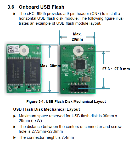
7. * * Onboard USB flash memory * *: CN7 9-pin socket, limited to 39mm × 29mm flash memory modules.
Board interface, pin definition, and dip jumper
1. Board layout, panel layout
Includes assembly structure diagram of motherboard 4HP/8HP, layout of RTM front and rear panels, marked with CPU, north-south bridge, network port controller, and all connector positions.
2. Definition of all connector pins
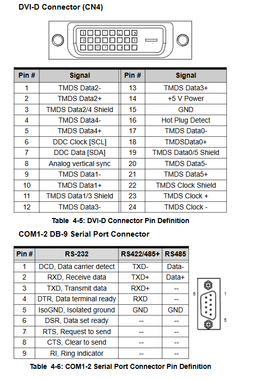
The complete table provides signals for each pin of USB, PS/2, DVI-I/DVI-D, DB9 serial port, parallel port, Gigabit Ethernet port, SATA, CF card, PMC, CPCI J1/J2/J3/J5 backplane connectors.
3. Switch and jumper settings
1. * * COM1/COM2 dip switch * *: SW1~SW4, SW5~SW8, switch RS232/422/485/485+four serial port modes by dip code;
2. * * Clear CMOS switch SW9 * *: Short circuit to clear BIOS and restore to factory;
3. JPX1 PMC IO Level Jumper: Default 3.3V, switchable 5V to adapt to different PMC daughter cards.
4. Definition of Front LED Status
PW power green light, GP universal blue light, WDT watchdog amber alarm light, HD hard drive read-write red light, distinguish the meaning of constant on/off/flashing status.
Hardware installation steps
The entire hardware assembly process emphasizes anti-static measures (anti-static wristbands, anti-static bags):
1. CPU and heat dissipation: Pre installed at the factory, not recommended for disassembly, replacement requires original factory thermal pads;
2. SO-DIMM memory installation: Double stacked slots, align with the foolproof notch and press to fix;
3. CompactFlash card: Remove the fixed bracket, insert it and lock it to prevent detachment;
4. 2.5-inch SATA hard drive: equipped with DB-6910SAT adapter board, copper pillar, and screw fixation;
5. PMC sub card installation: adjust JPX1 level, assemble DB-6965PMC adapter card, and lock panel bracket;
6. USB flash module: After fixing the copper pillar, connect it to the CN7 socket;
7. Install the motherboard into the 6U CPCI chassis: align with the guide rail, insert the backplane connector, lock the puller and panel screws;
8. Installation of RTM adapter module: correspond to the motherboard model one by one. Mismatching may damage the hardware.
Driver installation
1. * * Driver source * *: Comes with ADLINK All in One CD or official website download, path ` cPCI \ cPCI-6965 `;
2. Windows XP standard installation sequence: chipset driver → graphics card GMA X3100 driver → dual gigabit network card driver;
3. SCSI driver (RTM with SCSI only): Device Manager manually specifies the directory for installation;
4. System support instructions: Linux and VxWorks need to apply for dedicated BSP and driver packages from Linghua.
Tool software functionality
1. Watchdog Timer WDT
-Hardware based on IT8712F Super IO (LPC address 0x2E);
-The timing range is 1 second to 255 minutes, and the whole machine will automatically reset after timeout;
-Software functions: enable/disable, reload timing, WDT alarm LED control;
-Comes with complete example code in C language under DOS for dog feeding development in application programs.
2. PXE network pre boot environment
Onboard dual gigabit network card supports PCIe diskless boot; Deployment conditions: DHCP+TFTP+PXE servers within the network, capable of loading operating system images through network ports.
AMIBIOS 8 BIOS Setup Manual
Press * * Delete * * to enter BIOS during startup, and there are 7 major configuration menus:
1. * * Main interface * *: System time, date, CPU/memory hardware information;
2. * * Advanced Settings**
-CPU configuration: virtualization, multi-core, SpeedStep, C-State energy-saving switch;
– IDE/SATA、 Soft drive, Super IO serial/parallel port address and mode;
-Hardware Health: Real time reading of CPU temperature and various voltages;
-Serial port remote console redirection, USB compatibility mode configuration;
3. * * PCI/PnP plug and play * *: IRQ/DMA channel reserved, compatible with older ISA devices;
4. * * Boot boot settings * *: boot sequence, fast boot, silent OEM screen, PXE network boot switch;
5. * * Security * *: Administrator/user two-level startup password, clear user password;
6. Chipset chipset: USB port quantity switch, HD audio, network card PXE ROM initialization;
7. * * Exit menu * *: Save exit, discard modifications, load optimal/fail safe default parameters.