ADLINK cPCI-6840 series 6U CompactPCI single board computer
Product series composition and form differentiation
1. Differences in SBC cores between two motherboards
|Model | Panel peripherals | PMC slot | 2.5-inch hard drive slot|
|CPCI-6840 | No front VGA/PS2 keyboard and mouse | Up and down dual PMC (PMC1+PMC2) | PMC1 position can accommodate hard drives|
|CPCI-6840V | Front DB15 VGA+PS2 keyboard and mouse | Only on PMC2 slot | No space below to install hard drive|
2. Three matching RTM transition modules (6U rear IO board)
1. cPCI-R6840: rear DVI, external SCSI interface, compatible with SCSI PMC card;
2. cPCI-R6841: rear PS2 keyboard and mouse, built-in 2.5-inch hard drive compartment;
3. cPCI-R6841P: with PIM expansion slot, used for telecom PMC rear IO expansion.
3. Standard specifications and appearance
-Specification: Standard 6U CompactPCI, 4HP (20.32mm) single slot width; Motherboard size 233.35 × 160mm, RTM 233.35 × 80mm.
Core Hardware Specifications (Product Introduction Chapter)
1. Processor and chipset
– CPU:Intel Pentium M / Celeron M, Main frequency 1.3~2.0GHz, 1MB L2 cache, 400MHz front-end bus; Supports LV/ULV low voltage versions (OEM exclusive).
-North Bridge: Intel 855GME (integrated 3D graphics card, sharing up to 32MB of video memory, supporting VGA/LVDS dual display);
-Nanqiao: Intel 6300ESB, integrated watchdog, dual PCI bus, and multiple storage interfaces;
-PCI bridge: The PLX PCI-6540 universal three-mode bridge supports transparent/opaque mode, can be used as * * system slot/peripheral slot * *, supports PICMG2.1 hot plug, and the peripheral slot supports hot plug.
2. Memory
Dual 200 pin SO-DIMM slots, PC2700 DDR333 ECC memory, maximum total capacity 2GB.
3. Bus and Expansion Capability
1. CompactPCI bus: 64bit/66MHz, backward compatible with 32/64bit 33MHz;
2. PMC expansion: up to 2 64bit/66MHz PMC slots, upper layer PMC2 supports rear J24 IO (PICMG2.3);
3. Storage interface:
-Onboard main Ultra ATA100 IDE (connected to 2.5-inch hard drive);
-Secondary IDE, dual SATA 150MB/s routing to RTM;
-RTM is equipped with a CF card slot (IDE compatible);
4. Network port (3-channel gigabit 10/100/1000Mbps):
-LAN1/LAN2: Intel 82546GB dual gigabit, 64 bit PCI, using PICMG2.16 packet switched backplane/rear RTM;
– LAN3:Intel 82541PI,32bit PCI, Front RJ45 management network port, BIOS switchable.
4. Complete set of IO peripherals
-Display: Front VGA (only 6840V), Rear VGA/DVI/LVDS;
-Serial port: COM1 front RJ45, COM2 rear RTM RJ45, standard RS232 DTE;
-USB 2.0: front 2 ports, rear RTM 2 ports, single port 0.5A overcurrent protection;
-Keyboard and mouse: 6840V front PS2, all models support rear PS2;
-System indicator lights (front): hard drive red, power green, hot swappable blue, watchdog yellow; Front reset button.
5. Environmental and electrical parameters
1. Temperature and humidity
-Work: 0~55 ℃ (forced air cooling 50CFM); Storage -20~80 ℃; 5%~95% without condensation;
2. Vibration and impact
-Working at 0.5Grms (with hard drive); Non working 1.88Grms; Impact 15G peak value;
3. Power consumption: 1.6G CPU+512MB+20GB hard drive full load>61.2W;
4. Power supply: CompactPCI standard+5V/+3.3V/+12V/-12V; The power ramp circuit meets the hot plug specifications and automatically resets when the voltage is below the threshold.
6. Manage hardware
-BMC substrate management controller ATMEGA128L, compatible with IPMI v1.5 and PICMG2.9 system management bus;
-W83627HG hardware monitoring chip: collects onboard voltage and temperature, and automatically shuts down protection when exceeding the threshold;
-CR2032 button battery provides independent power supply for RTC and BIOS configuration storage.
Definition of jumpers, switches, and all interface pins
1. Motherboard jumper function
-JP1: Forcefully ground SYSEN # as a system slot (external slots are prohibited from short circuiting);
-JP3: Clear CMOS RTC and BIOS configuration;
-SW1: Front hardware reset button;
-Mini switch for pop-up device: controls hot plugging and power on, and reports ENOM in place signal.
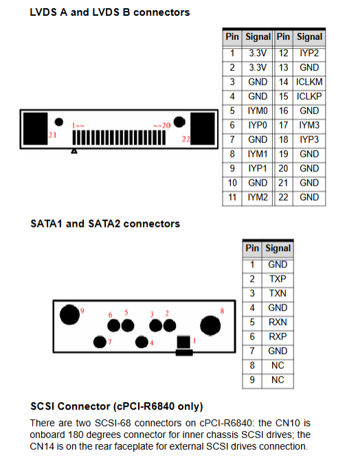
2. Complete definition of all interface pins
Includes front VGA/PS2/RJ45 Ethernet ports/RJ45 serial ports/USB, CompactPCI J1/J2/J3/J5 backplane connectors, PMC slots, 44 pin IDE;
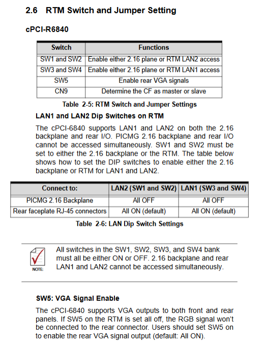
3. RTM side switch jumper
-LAN dial-up: switch to gigabit network connection PICMG2.16 backplane/rear RJ45 (cannot be enabled simultaneously);
-SW5: Switch rear VGA output;
-CF master-slave jumper: Set CompactFlash as the master/slave IDE device;
4. Supporting drawings: motherboard front and back, RTM physical layout, schematic diagrams of various connector pins.
Whole machine hardware installation process
Step by step complete installation guide, all operation requirements: anti-static wristband/workbench:
1. Assembly of CPU and heat sink;
2. SO-DIMM memory installation;
3. Installation of 2.5-inch IDE hard drive on motherboard (distinguishing between 6840/6840V fixed structures);
4. RTM side hard disk and CF card assembly;
5. PMC sub card installation (lower level extensions cannot be used when the hard disk occupies PMC1);
6. RTM transition module docking (must match the corresponding motherboard model, mixing may damage hardware);
7. CompactPCI chassis full machine insertion, hot plug and power on verification (blue hot plug light off indicates in place readiness).
Windows Driver Installation (Win2000/XP/2003 Server)
Standard installation sequence: chipset driver → VGA graphics card driver → three gigabit network card drivers;
1. Chipset: Intel INF installation tool, restart after installation;
2. Integrated graphics card: 855GME display driver package;
3. Network card: Intel PROSet tool compatible with 82546GB/82541PI;
4. Addendum: Linux and VxWorks BSP need to contact Linghua technical support for assistance.
System Tools (Watchdog WDT+PXE Network Boot)
1. Dual level watchdog timer (integrated with 6300ESB South Bridge)
-Accuracy: Adjustable from 1 μ s to 10 minutes, 35 bit subtraction counter;
-Two level mechanism: The first level triggers an interrupt upon timeout, and if the dog is not fed, the second level outputs a hardware reset signal WDT \ _TOUT;
-Two modes: watchdog dual level mode and free single-stage flipping mode;
-Supporting: Front yellow WDT running indicator light, providing DOS testing tool HRWDT.EXE, with register read/write unlock process and programming steps.
2. Preboot Execution Environment for PXE
Support remote boot system via gigabit network, deployment requires DHCP+TFTP+PXE server, and the manual provides environment setup steps and supporting tool paths.
IPMI v1.5 Intelligent Platform Management Complete Guide
Based on the onboard BMC controller, it is used for remote monitoring, remote power on/off, and fault alarm, and is a highly available core function in telecommunications
1. Standard IPMI supports command set: device ID, self detection, watchdog control, sensor reading, FRU hardware information, event alarm;
2. OEM extension specific instructions: firmware version read, remote power on/off, SMBus switch, fault debugging variable read, IPMB address rescan;
3. IPMB address mapping, onboard sensor list (3.3V/5V/12V voltage, system temperature, BMC watchdog);
4. Known limitations: BMC does not have an independent RTC, and the power on timestamp is reset to zero; Sensor SDR flash read-only;
5. Supporting reference standards: IPMI v1.5, PICMG2.9 specification documents.
Safety operation standards
1. Installation and maintenance must be anti-static; Do not block the cooling air duct of the chassis;
2. Risk warning for lithium battery replacement (mismatched batteries pose a risk of explosion);
3. Water ingress, cable damage, and hardware deformation must be handed over to professional maintenance personnel, and self opening of covers is prohibited;
4. Use only power within specifications and keep away from moisture, heat sources, and liquids.