ADLINK NuPRO-595 series half length Socket 7 industrial motherboard
Comparison of core differences between NuPRO-595/596 products
Both are 185 × 122mm half length ISA industrial boards, with Socket7 architecture and Intel 430TX chipset. The core difference is only the network port:
|Parameters | NuPRO-595 | NuPRO-596|
|Processor | Pentium MMX, low-power Pentium, AMD K6-2/K6-3, Cyrix MII | Same as 595|
|Chipset | Intel 82430TX Northbridge+82371EB Southbridge | Completely Consistent|
|Cache | Onboard 512KB L2 Cache | Completely Consistent|
|Memory | Single 168 pin SDRAM DIMM, maximum 128MB | Completely Consistent|
|Display | C&T 69000, supports CRT+LCD dual display | completely consistent|
|Serial port | COM1 RS232, COM2 switchable RS232/422/485 | Completely consistent|
|Watchdog | 0~255 seconds/minute programmable | completely consistent|
|Hardware Monitoring | Winbond W83781D (Voltage/Fan/Temperature/Chassis Open Cover Detection) | Completely Consistent|
|Storage | Ultra DMA33 IDE, floppy drive, DOC solid-state drive slots | Completely consistent|
|Network card | Onboard Intel 82559 10/100M, supports WOL remote wake-up | No onboard network port|
|I/O | 2 serial ports+1 parallel port+USB 1.0 | Completely consistent|
|Size/Power Supply | Half length ISA board, supports AT/ATX power supply | Completely consistent|
Product hardware specifications and core functions
1. Processor and bus
-Socket 7 slot, CPU clock speed 166-400MHz, 66MHz system bus; Supports low-voltage embedded Pentium and AMD K6 series low-power CPUs, suitable for fanless industrial control scenarios.
-PCI+ISA dual bus architecture, compliant with PICMG industrial specifications.
2. Storage capacity
1. Memory: Single slot PC133 SDRAM, maximum 128MB;
2. IDE: Single channel Ultra DMA33 main IDE, supporting 2 hard drives/optical drives;
3. floppy drive: compatible with 360KB~2.88MB full specification floppy disks;
4. DOC slot: Onboard DiskoChip solid-state flash memory socket, address D800-DFFF, capacity 2-144MB, capable of booting industrial computers without a disk.
3. Graphic display (C&T 69000)
-Onboard 2MB video memory, simultaneously driving CRT display and LCD screen;
-CRT up to 1280 × 1024 8-bit; Supports DSTN/TFT monochrome/color screens, 12/18/24 bit LVDS panels;
-Independent 5V/3.3V LCD screen power jumper, compatible with different industrial screens.
4. Communication I/O interface
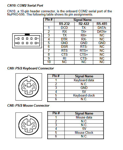
1. Serial port: COM1 fixed RS232; COM2 switches RS232/422/485 via JP11/JP12/JP13 jumper, with full interface 2KV ESD protection;
2. Parallel port: SPP/ECP/EPP three mode, 4KV electrostatic protection;
3. USB 1.0: Two onboard pins, independent overcurrent protection;
4. PS/2 keyboard and mouse independent pin, additional external keyboard interface;
5. Ethernet port (only 595): Intel 82559 PCI 100Mbps, IEEE802.3x flow control, auto negotiation, WOL network remote boot.
5. Industrial control characteristic hardware modules
1. Programmable watchdog WDT
The time base can be selected in seconds/minutes, with a range of 0-255. If it exceeds the time limit, the entire machine will automatically reset; Provide 8086 assembly configuration example code, which can reset the timer by feeding the dog with keyboard and mouse.
2. Full hardware monitoring W83781D
Real time collection of CPU voltage, motherboard 3.3V/5V/12V/-12V, CPU/chassis fan speed, CPU temperature, and external system temperature; Equipped with chassis lid opening alarm detection.
3. Power management
AT/ATX dual power supply compatibility; Supports modem ringing startup, WOL remote startup, BIOS multi-level sleep (Doze/Standby/Suspend), and CPU frequency reduction for energy saving.
4. Basic onboard peripherals
Buzzer, hardware reset, power indicator light, hard disk read-write light, CPU fan temperature control socket.
6. Environmental and electrical parameters
-Working temperature: 0-60 ℃; Humidity of 5%~95% without condensation;
-Full load power consumption (K6-3 400MHz):+5V 11.8A,+12V 50mA, -12V 30mA;
Hardware installation (CPU/memory/jumper/interface definition)
CPU and memory installation steps
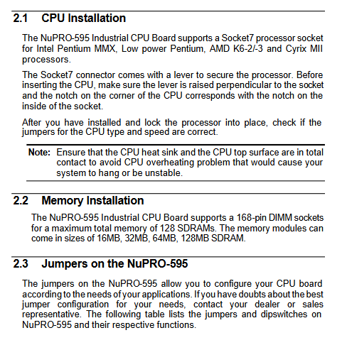
1. CPU: Lift the Socke7 lever and align it with the notch to install it. After locking, it must be matched with JP7 multiplier and JP9 core voltage jumper wires, and equipped with a heat sink to avoid overheating and crashing;
2. Memory: Single 168 pin DIMM slot, supporting 16/32/64/128MB SDRAM, fixed with a snap fastener.
All jumper functions (core configuration switch)
1. JP7: CPU multiplier jumper, matched with different clock speeds of Pentium/AMD/Cyrix;
2. JP9: CPU core voltage (multiple levels of 1.9V~2.8V);
3. JP4/JP5: CPU IO voltage switching between 2.5V/3.3V;
4. JP1: LCD screen power supply 3.3V/5V selection;
5. JP2: Clear CMOS (short circuit 1-2 to clear BIOS settings, 2-3 runs normally);
6. JP11/JP12/JP13: COM2 serial port protocol switching (232/422/485);
7. JP6: External system temperature sensor;
8. JP8: Chassis cover opening detection sensor pin.
Complete pin definitions for all onboard connectors
Including motherboard layout drawings and all pin signals:
-CN4 multifunctional pins: power switch, reset, power LED, hard disk LED, chassis speaker, keyboard lock;
-CN5 50pin LVDS LCD screen interface: compatible with various TFT/DSTN screens;
– IDE、 Soft drive, VGA, RJ45 Ethernet port, dual serial port, parallel port, PS2 keyboard and mouse, USB, CPU fan, ATX power plug;
Supporting LED status description: Green light link and yellow light data flashing distinguish 10/100M network speed.
Award BIOS Complete Setup Manual
Press Del to enter the BIOS main menu. Detailed explanation of all industrial control specific parameters:
1. Standard CMOS settings
System time, IDE hard disk automatic recognition, floppy drive type, display output (CRT only/LCD only/dual display), startup error shutdown strategy.
2. BIOS Function Settings
Virus protection, CPU internal and external cache switch, power on self-test speed, boot sequence (floppy disk/hard disk/network/SCSI), digital lock, A20 address line, boot password, PXE network boot switch.
3. Chipset settings
SDRAM timing, memory holes, Spread spectrum (EMI testing), CPU overheating warning, chassis cover opening buzzer alarm, real-time read-only monitoring of various voltages.
4. Power Management PM
APM energy-saving, video shutdown strategy, multi-level sleep timing, CPU sleep speed reduction, WOL/modem remote boot, fan sleep stop, hardware wake-up interrupt configuration, supports 16 types of industrial LCD screen selection.
5. PNP/PCI configuration
Plug and play switch, IRQ/DMA resource manual allocation, compatible with old ISA industrial control cards without conflicts.
6. Integrated peripherals
IDE PIO/UDMA mode, serial parallel mode, USB keyboard, onboard VGA/network card enable switch.
7. Auxiliary functions: administrator/user dual password, loading factory/optimal defaults, automatic hard disk detection, saving/discarding, exiting BIOS.
Driver Installation Intel PIIX Bus Master IDE driver (Win95 only)
Installation prerequisites and step-by-step process, deleting real mode IDE drivers, installing file paths, troubleshooting, and improving hard disk DMA transfer speed.
C&T 69000 graphics card driver (Win95/98/NT4.0)
The installation steps for each system control panel require NT to pre install SP5 patch to adapt to LCD industrial display output.
Intel 82559 100Mbps Network Card Driver (NuPRO-595 only)
1. Support systems: Win95/98/NT, NetWare, SCO Unix, Linux, DOS group drivers;
2. Supporting diagnostic tools: automatic detection of network cards, viewing MAC/speed, loop testing, batch installation of drivers;
3. Hardware features: Bus master control, full duplex, Magic Packet remote wake-up.
Hardware Doctor Hardware Monitoring Tool
Windows platform monitoring software, paired with W83781D chip:
1. Monitoring items: Vcore, 3.3V/5V/± 12V voltage, three-way fan speed, CPU/system temperature, chassis cover opening;
2. Function: Custom upper and lower threshold values, over limit pop-up window+buzzer alarm, fault counting filtering, parameter saving/restoring to default;
3. Operating mechanism: The backend resides in the tray program, and only the 3-pin speed measuring fan supports speed reading. When the temperature exceeds the threshold, an active warning is issued to protect the CPU.